Quick Start
Power On and Connection
Power On
TIP
Note: Before powering on, confirm that the handheld emergency stop, back emergency stop, and mobile platform emergency stop are in the non-triggered position
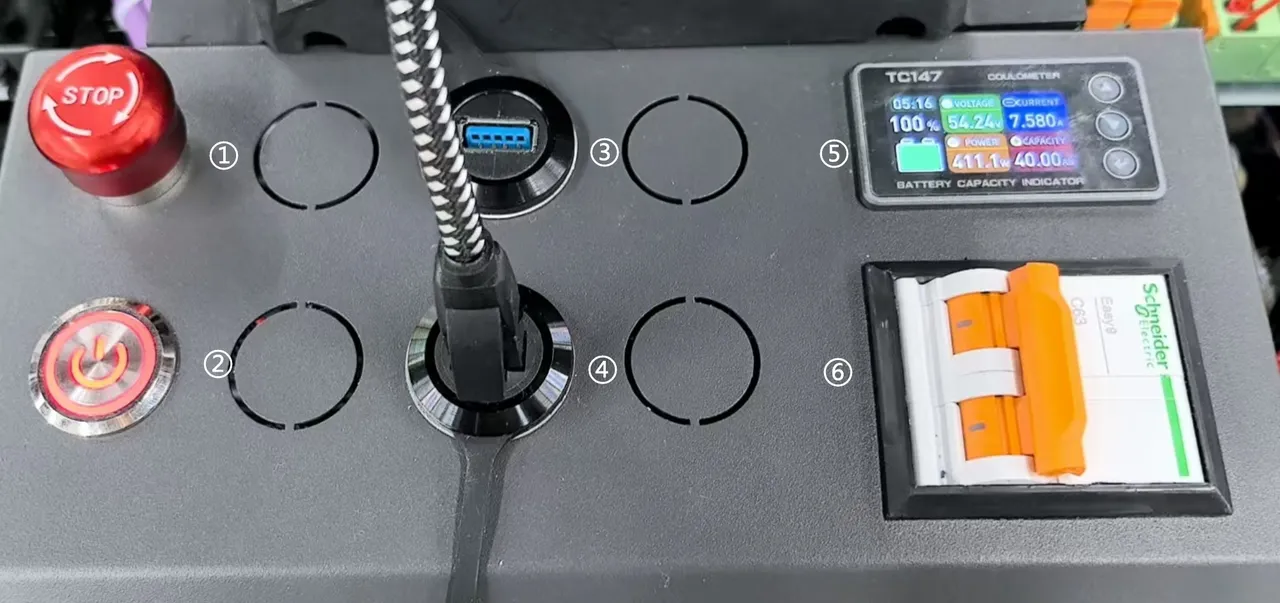
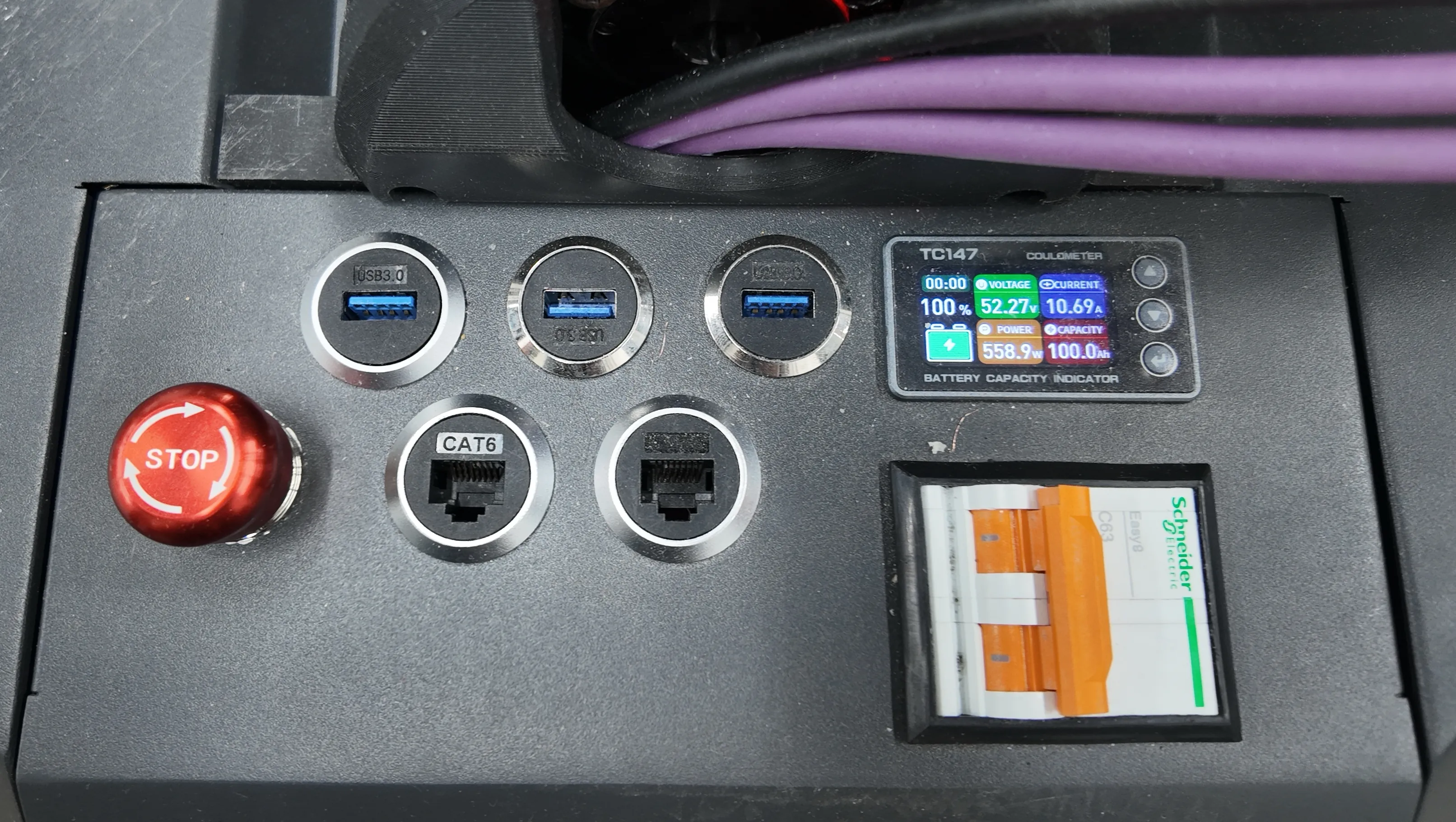
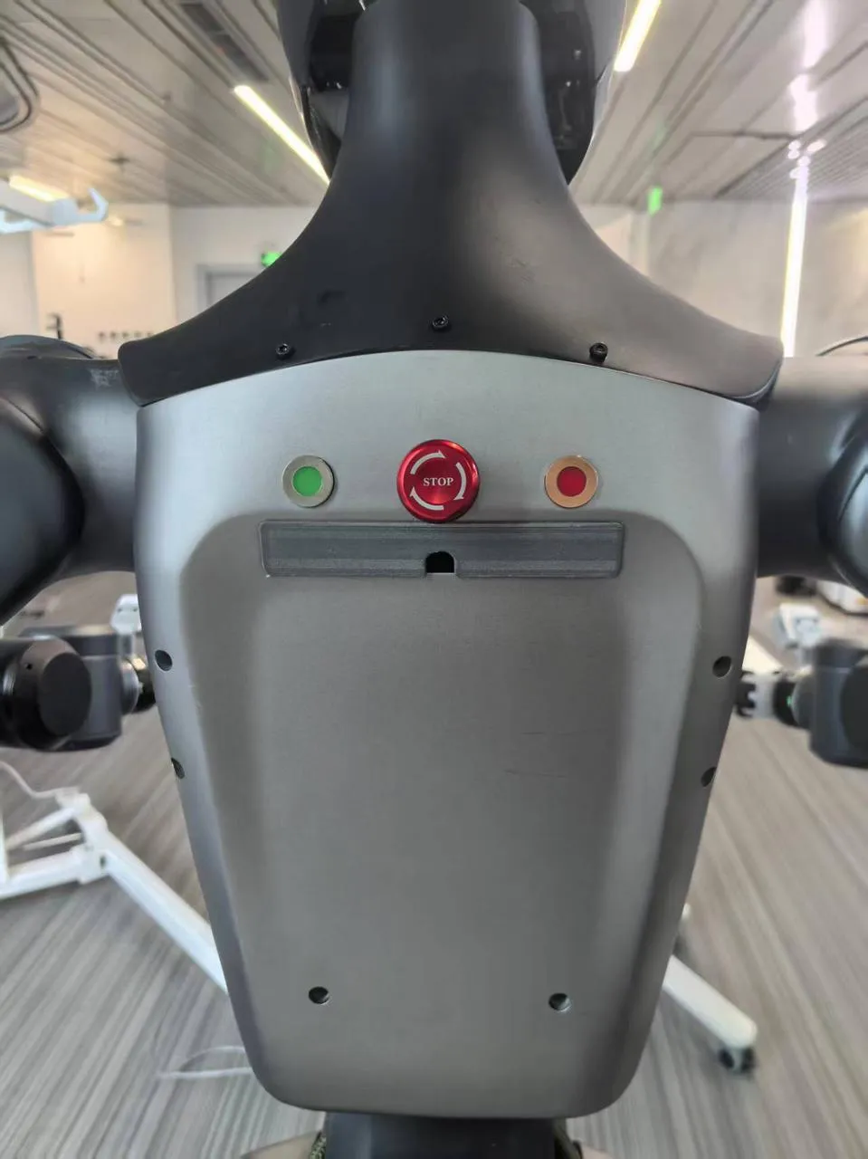
The device main power switch is located at the rear of the mobile platform, as shown in the figure. The function items are described as follows:
- ① Mobile platform emergency stop button: Rotary reset red mushroom head button, needs manual reset after being pressed.
- ② Collection/Inference host switch: Short press to turn on/off, wait 60s after pressing; red light indicates powered on state.
- ③ USB port: For connecting VR teleoperation devices
- ④ Ethernet port: Internally connected to motion control unit LAN port 4, fixed IP 172.16.1.20.
- ⑤ Battery level display screen: Shows current battery level in real-time.
- ⑥ Device main power switch: Main power switch for robot and collection/inference host.
Turn on ⑥ device main power switch, ② collection/inference host switch and ⑤ battery level display screen will light up simultaneously, wait 3~5 minutes for the system to fully start.
INFO
- The collection/inference host can be turned off to maintain battery level when not in use. Press and hold ② for 1s then release, and it will shut down after 60s;
- Before turning off the main power, it is recommended to shut down the host first.
Connection
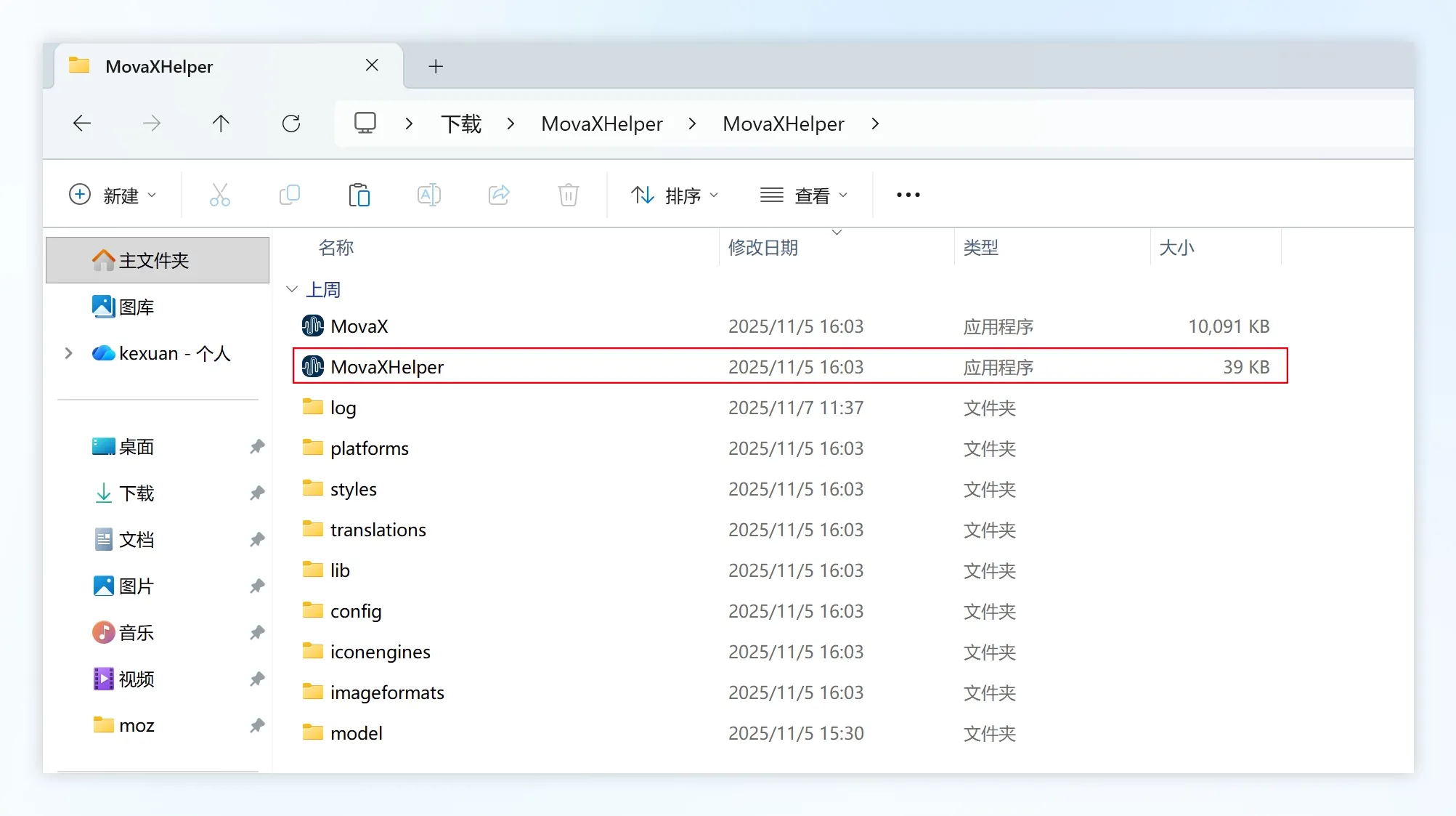 Using Windows PC as an example, download the MovaXHelper software package and extract it, enter the folder and double-click the MovaXHelper.exe icon to open the HMI.
WARNING
Please store the software package in a non-Chinese character path, otherwise it cannot be opened normally.
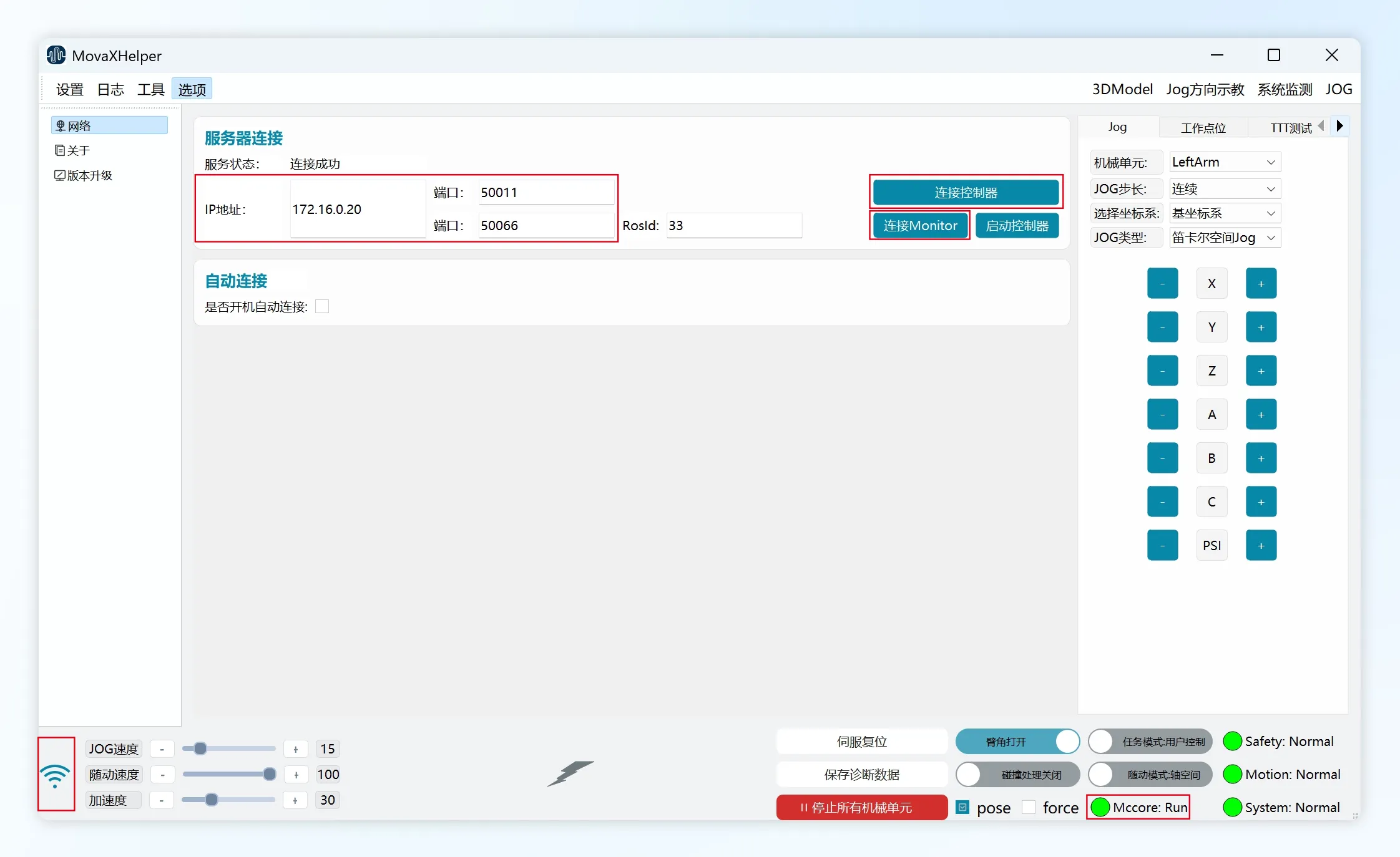 After the system starts, the host computer (IP must be in the same network segment as ④) can establish connection with the device via Ethernet cable.
First click "Connect Monitor", the interface will indicate successful connection, and the "Mccore" status light in the lower right corner will be green with status showing "Run", indicating successful connection.
Then click "Connect Controller", the interface will indicate successful connection, and the signal status in the lower left corner of the interface will show full bars, indicating successful connection.
Tablet Connection
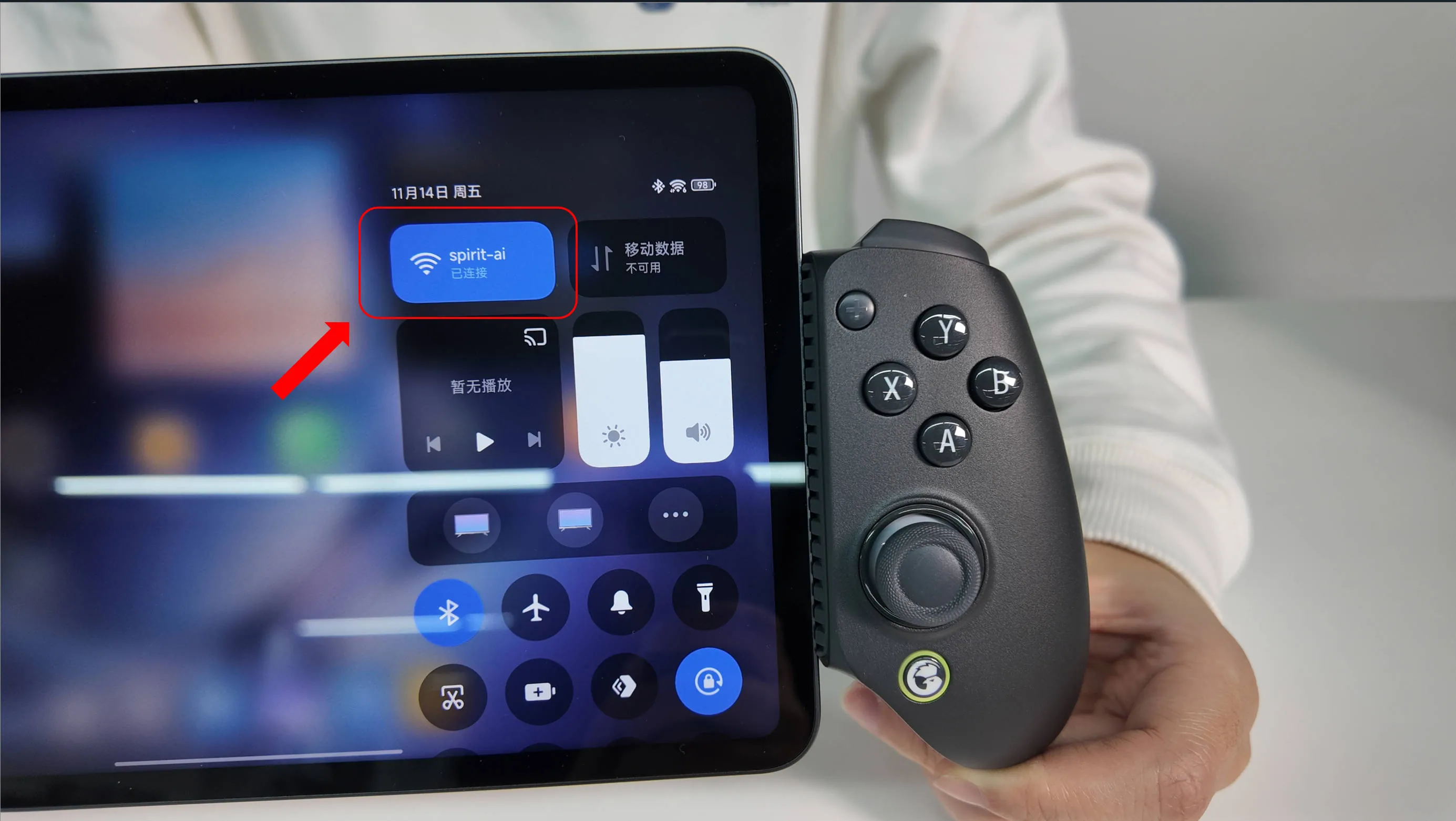 Connect the tablet to the robot's built-in WiFi hotspot "MOZ1-0900x" through WiFi settings, default password is "spirit-ai".
 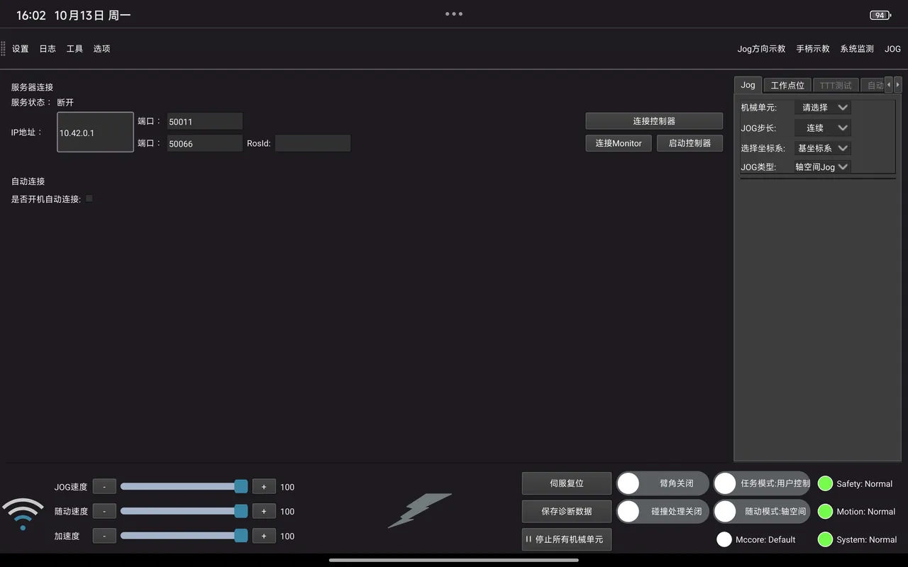 Launch the desktop application "SpiritAI MovaX", wait for the interface to start. IP address and port are shown in the figure, software usage is the same as PC version.
User Permission Login
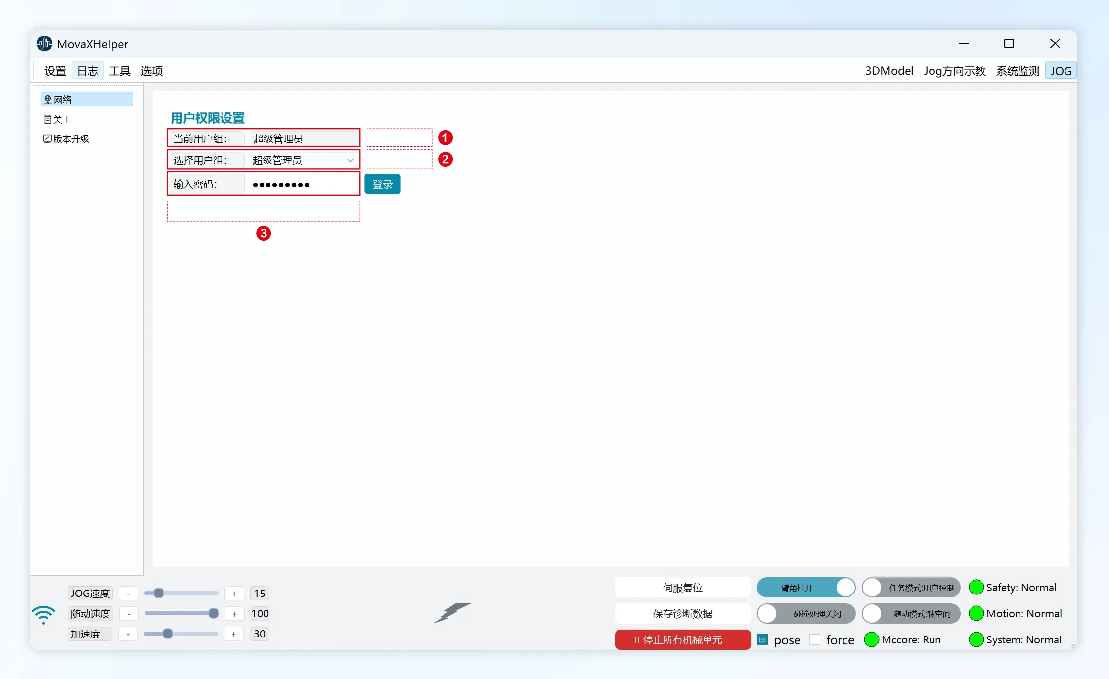 The MovaX system has four built-in user levels, from lowest to highest operation permissions: Normal User, Data Collector, Developer, and Super Administrator. After connecting to the controller, it defaults to Normal User login; switching to other permission users requires a password.
- ① Current user group: Currently logged-in user group.
- ② Select user group: Select the user group to log into.
- ③ Enter password: Each user group's permissions and default passwords are as follows:
| User | Password | Permissions |
|---|---|---|
| Normal User | 123456 | Settings: User login, zero point calibration, parameter settings, peripheral settings, teleoperation settings Logs: HMI logs Tools: Set work points, servo status Options: Network, about, version upgrade JOG: Jog, work points Mechanical units: Power on/off |
| Data Collector | 123456 | Settings: User login, zero point calibration, parameter settings, peripheral settings, teleoperation settings Logs: HMI logs Tools: Set work points, servo status Options: Network, about, version upgrade JOG: Jog, work points Mechanical units: Power on/off, joint impedance |
| Developer | spirit | Settings: User login, zero point calibration, end tool parameters, force control parameter settings, parameter settings, peripheral settings, teleoperation settings Logs: HMI logs Tools: TTTTTest points, force sensor calibration, set work points, servo status, servo parameter settings, diagnostic data settings, parameter version management Options: Network, about, version upgrade JOG: Jog, work points, TTTTest, auto calibration Mechanical units: Power on/off, joint impedance, collision detection, drag mode |
| Super Administrator | spirit-ai | Settings: User login, zero point calibration, end tool parameters, force control parameter settings, parameter settings, peripheral settings, teleoperation settings Logs: HMI logs Tools: TTTTTest points, force sensor calibration, set work points, servo status, servo parameter settings, diagnostic data settings, parameter version management Options: Network, about, version upgrade JOG: Jog, work points, TTTTest, auto calibration Mechanical units: Power on/off, joint impedance, collision detection, drag mode |
Post-Startup Checks
Status Check
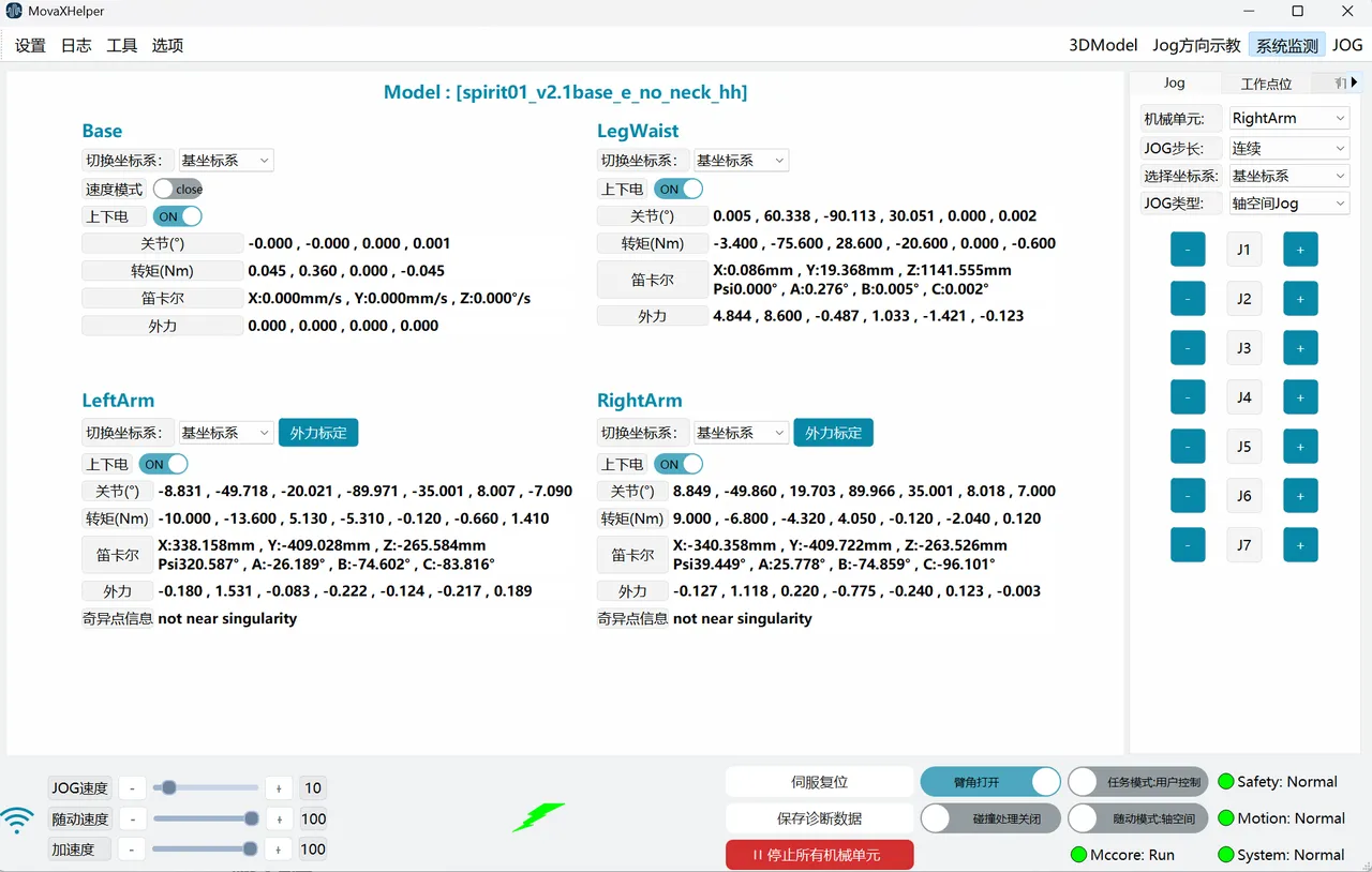
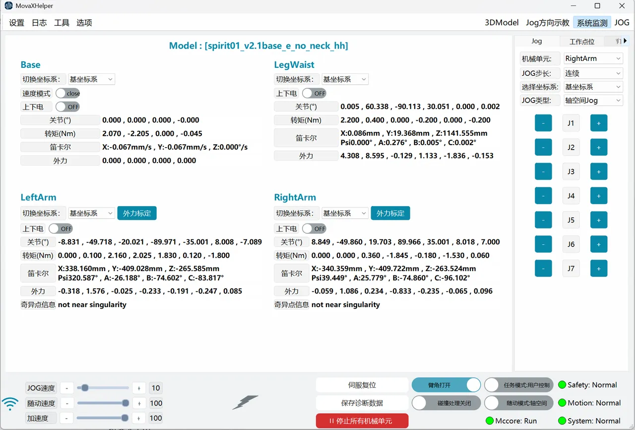 After successfully connecting to the controller, enter the function page through the "System Monitoring" button in the top status bar. At this time:
- Values on the system monitoring page should be constantly changing;
- The "Safety", "Motion", "System" status lights in the lower right corner of the interface should be green, with status showing "normal";
If the above two conditions are met, it indicates the robot started without abnormality; otherwise, please contact technical support.
Emergency Stop Check
| Mobile Platform Emergency Stop |
|---|
 |
| Back Emergency Stop |
|---|
 |
| Handheld Wireless Emergency Stop |
|---|
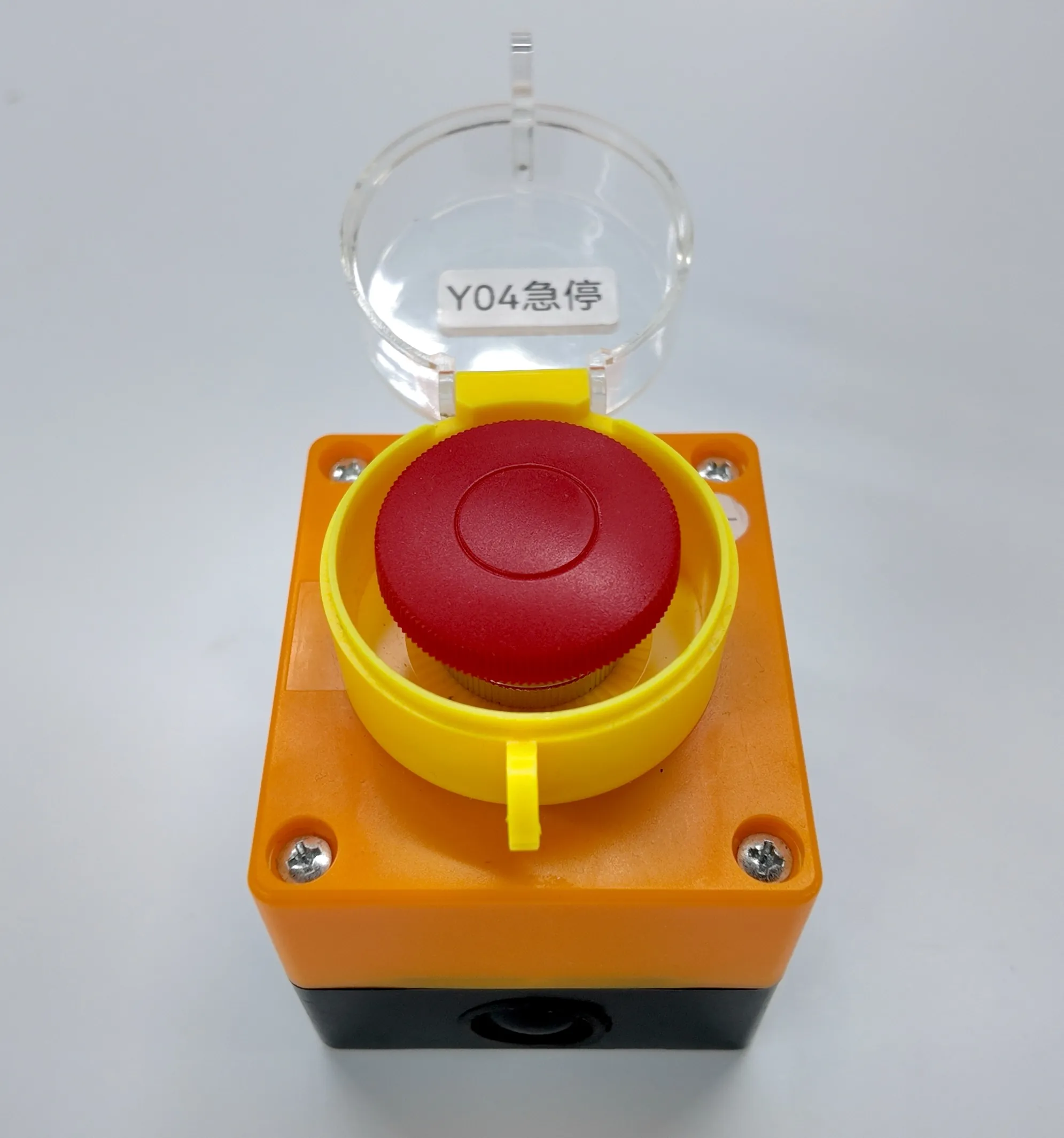 |
The robot has three emergency stop switches, two of which are rotary reset red mushroom head buttons located at the rear of the mobile platform and on the body's back; the other is a self-resetting handheld wireless emergency stop. The difference is that the red mushroom head button needs to be manually rotated to reset after being pressed, while the handheld emergency stop does not require this operation.
In the powered-on state, press the back emergency stop and check the feedback:
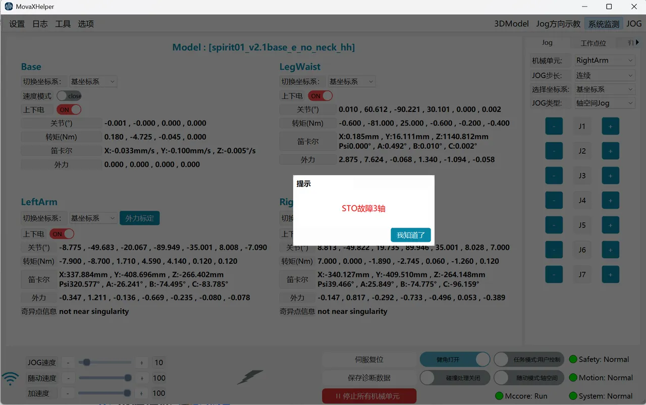
- If previously powered on, all mechanical units will power off simultaneously, accompanied by the sound of brakes engaging;
- The HMI interface will pop up an alarm "STO Fault X Axis", and in the "System Monitoring" interface, the power switches of all powered mechanical units will turn red, and all values will stop changing;
- After clearing the alarm popup, power-on is still not possible;
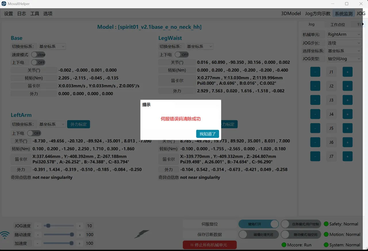
- Manually rotate the back emergency stop button to reset, click "Servo Reset" in the lower right of the HMI interface, the interface will pop up "Servo error code cleared", the interface returns to normal, and power on/off can proceed normally; in some cases, recovery cannot be achieved by "Servo Reset" alone, then go to the "Network" page and click "Start Controller" to restart, then perform "Servo Reset" after restart.
If the phenomena match the above four points, it indicates the robot's emergency stop function is normal; otherwise, please contact technical support.
Repeat the above steps to verify the mobile platform emergency stop and handheld wireless emergency stop respectively (the handheld emergency stop does not require manual reset in step four).
Power On/Off Check
On the "System Monitoring" page, each mechanical unit has a corresponding "Power On/Off" switch.
Hold the handheld emergency stop, maintain a certain distance from the robot, turn on each mechanical unit's "Power On/Off" switch in sequence and then turn them off, and check the feedback:
- When turning on the switch, the status shows "ON", and you can hear the sound of the corresponding mechanical unit releasing the brake;
- After the mechanical unit is powered on, it remains stationary with no runaway phenomenon;
- When turning off the switch, the status shows "OFF", and you can hear the sound of the corresponding mechanical unit engaging the brake;
- When no mechanical unit is powered on, the lightning symbol at the bottom is gray; when partially powered on, it shows yellow; when all are powered on, it shows green;
If the phenomena match the above four points, it indicates the robot's power on/off function is normal; otherwise, please contact technical support.
Zero Point Verification
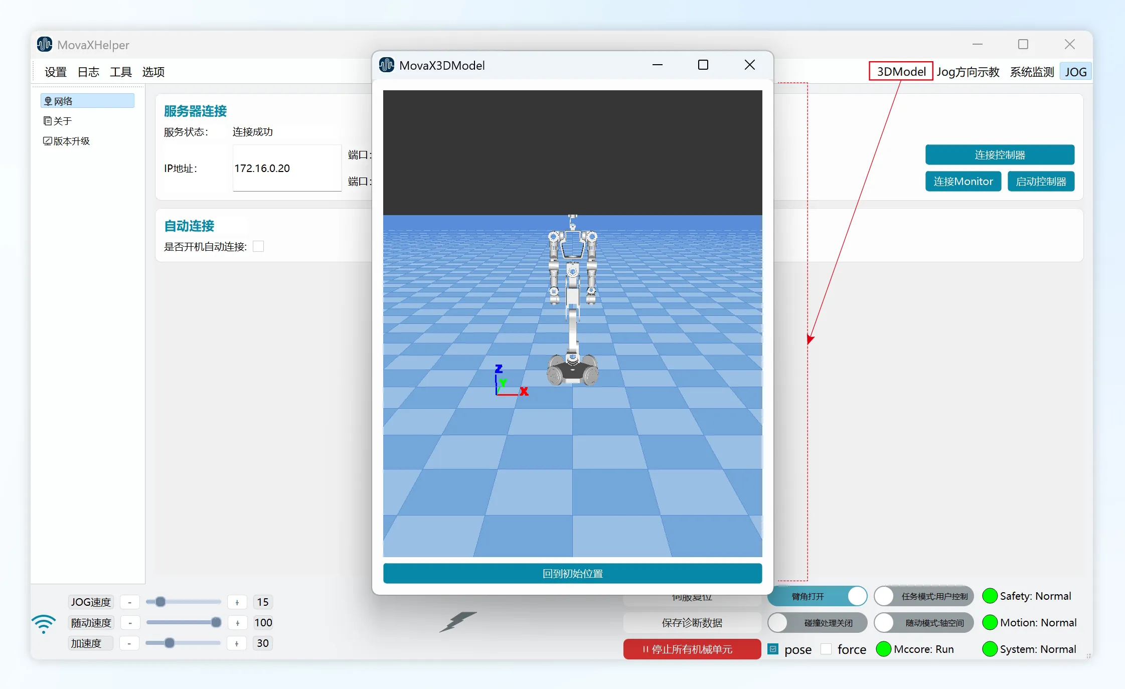
Open the floating panel through "3DModel" in the top status bar, check if the 3D model display pose is consistent with the robot's actual pose. If there is a large difference between the two, or if zero point loss has occurred, the zero point needs to be recalibrated; please contact technical support.
If the 3D model pose is basically consistent with the robot's actual pose, follow the steps below for further confirmation.
 |  |
|---|
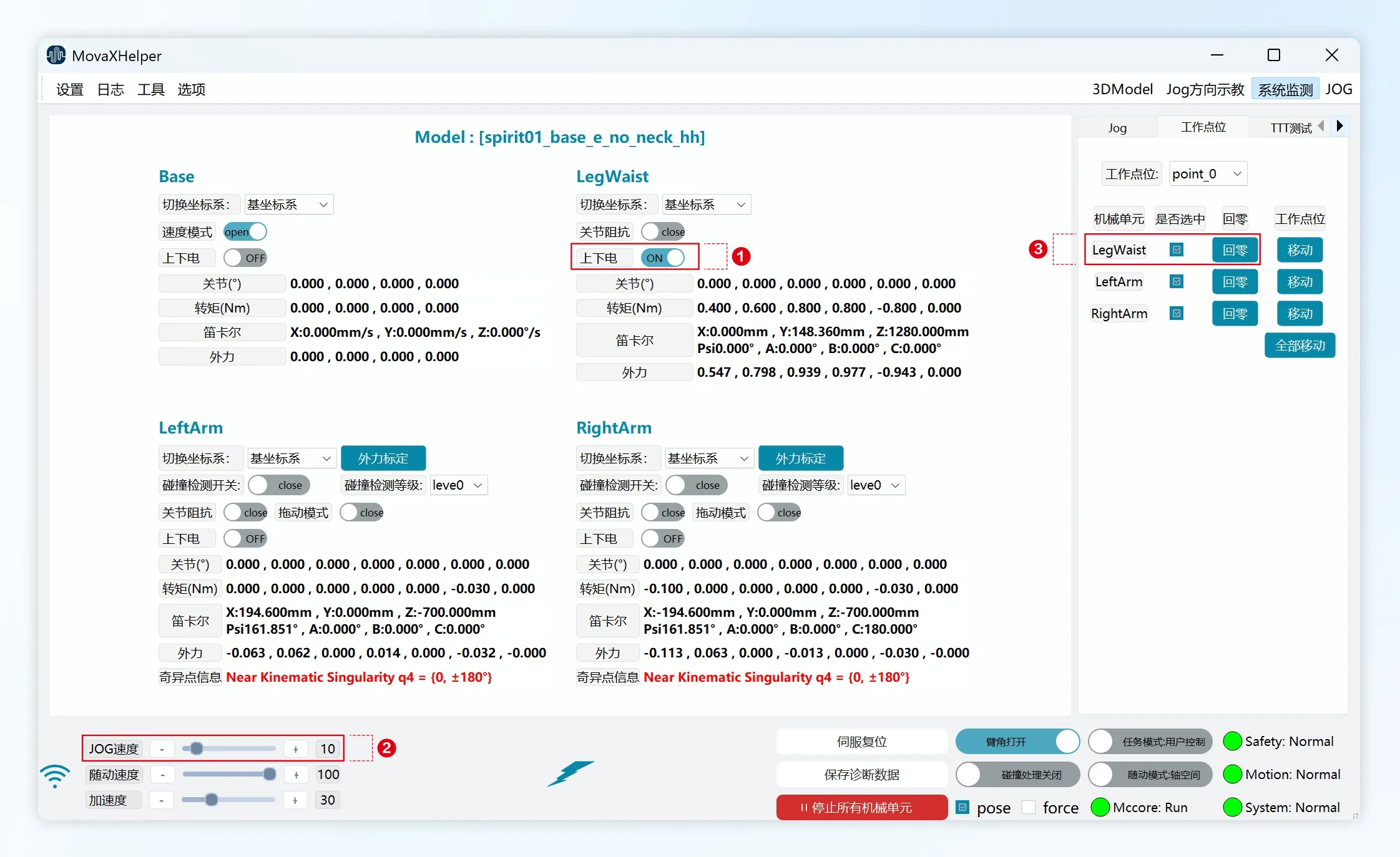
Hold the handheld emergency stop and maintain a certain distance from the robot:
- Power on a single mechanical unit through the "System Monitoring page" in the top status bar;
- Adjust the "JOG Speed" to below 10 through the bottom status bar;
- Enter the "Work Points" page in the right control panel, click "Return to Zero" for the mechanical unit in ①;
- Pay attention to the robot's pose at all times during the process to avoid collisions until the operation ends (Motion shows Normal at this point);
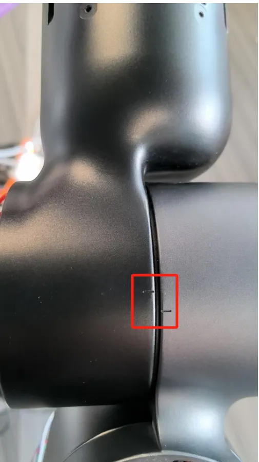
- Power off the mechanical unit in ①, check if the zero point calibration slots of each axis of the mechanical unit are aligned; if there is deviation, recalibration is required.