Mechanical Structure
Mechanical Requirements
Working Environment
This humanoid robot is designed for standard industrial and service scenarios. Its working environment parameters are as follows:
Working Temperature: -10°C ~ 50°C
Operating in extreme low temperatures (below -10°C) or high temperatures (above 50°C) may cause poor joint lubrication, reduced battery performance, or material aging. It is recommended to suspend operation and check equipment status when the temperature exceeds ±5°C of the range.
Working Humidity: ≤75% RH (non-condensing)
- High humidity environments (>75% RH) may cause electronic components to become damp, sensor malfunction, or internal short circuits. It is recommended to use moisture-proof sealed covers or environmental control devices (such as dehumidifiers) in high humidity environments.
IP Protection Rating: IP40
Special Notes:
- The robot should not operate in rain, snow, or outdoor environments, especially when humidity is >80% and there is rain.
- If environmental humidity remains above 60% for extended periods, it is recommended to perform internal drying and moisture-proof maintenance every 30 days.
- The robot body and joint areas should avoid direct contact with water or corrosive liquids.
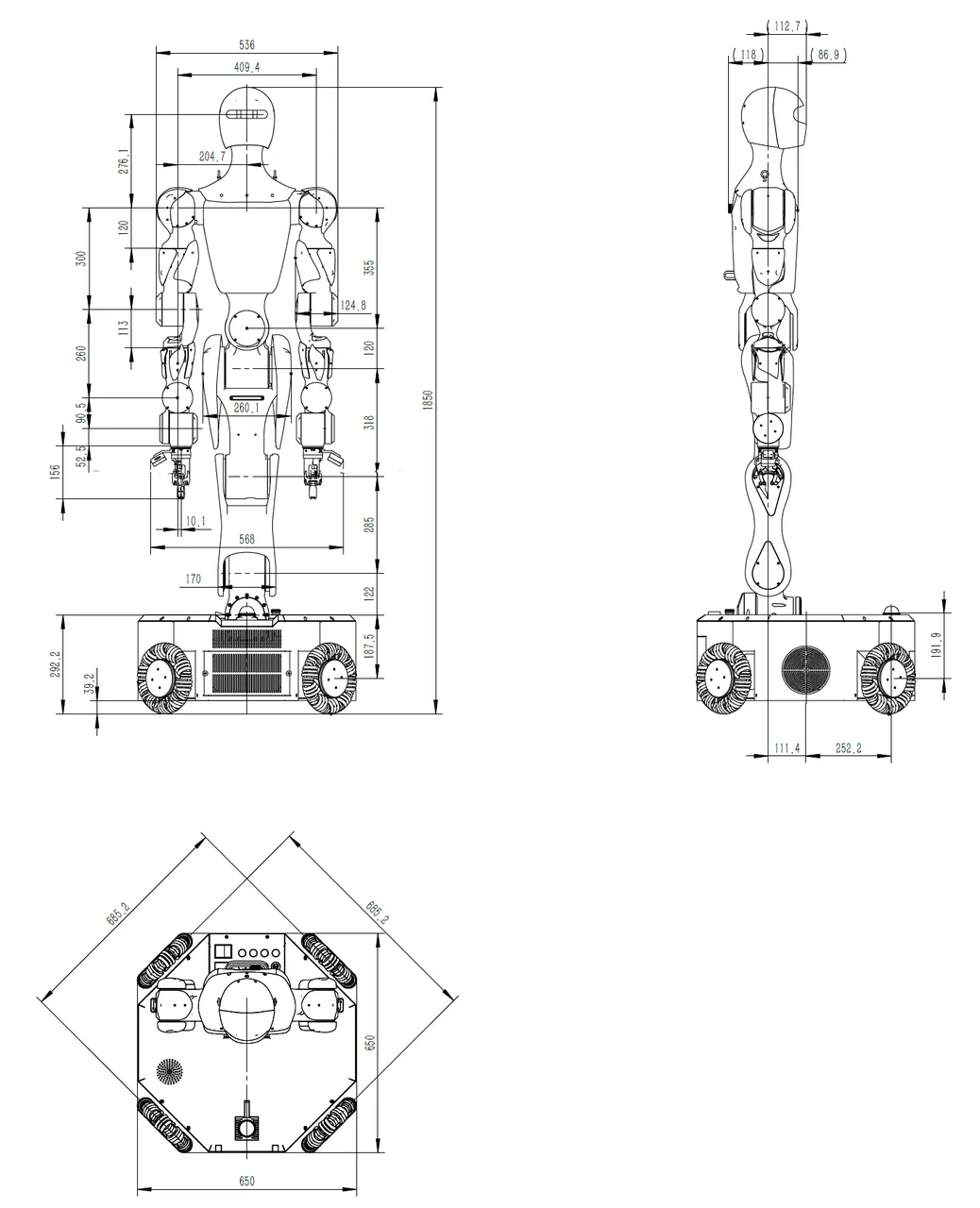
Overall Dimensions
The overall dimensions are as shown in the figure below:
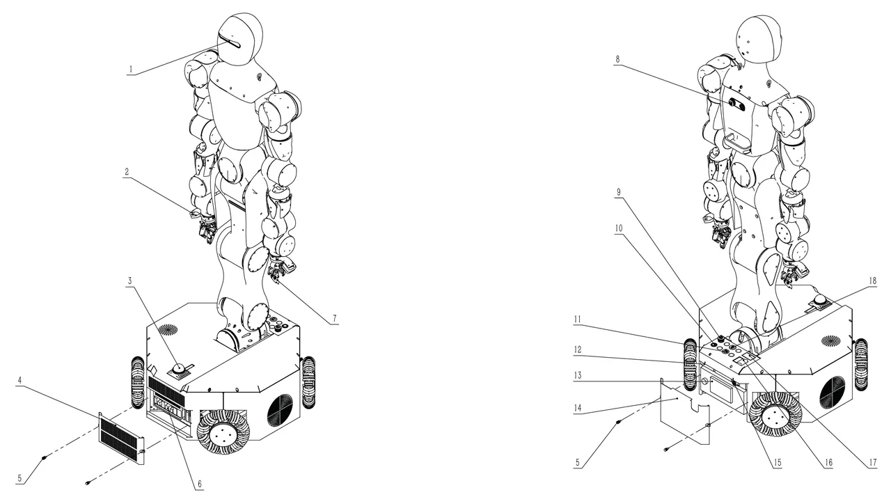
Main Components Diagram
The Moz1 has several sensors, actuators, interfaces, etc., as shown in the figure below:
| Component No. | Component Name | Quantity | Description |
|---|---|---|---|
| 1 | Head Camera (Intel D455) | 1 | For head perception |
| 2 | Wrist Camera (Intel D405) | 2 | For wrist perception |
| 3 | LiDAR (MID-360) | 1 | SLAM |
| 4 | Host End Cover | 1 | For inference host interface maintenance |
| 5 | Hand Screws | 4 | For securing host end cover and battery end cover |
| 6 | Inference Host Interfaces | 1 x USB 3.2 Gen 2x2 port(s)(1 x USB Type-C®) 1 x USB 3.2 Gen 2 port(s) (1 x Type-A) 3x USB 3.2 Gen 1 port(s) (2 x Type-A, 1 x USB Type-C®) 4 x USB 2.0 port(s) (4 x Type-A) 1 x HDMI® port 1 x DisplayPort 1 x Intel® 2.5Gb Ethernet | Head camera and wrist camera connection |
| 7 | Two-Finger Gripper | 2 | End effector |
| 8 | Back Emergency Stop Button | 1 | For stopping all robot movement in emergencies |
| 9 | Mobile Platform Emergency Stop Button | 1 | For stopping all robot movement in emergencies |
| 10 | Host Power Button | 1 | For host startup, shutdown, and forced shutdown |
| 11 | Ethernet | 1 | For robot motion controller connection |
| 12 | Battery Power Interface | 1 | Lithium battery power interface |
| 13 | Lithium Battery | 1 | For powering the entire robot |
| 14 | Battery End Cover | 1 | For securing the lithium battery |
| 15 | Charging Interface Aviation Plug | 1 | Charger connection interface |
| 16 | Circuit Breaker | 1 | For starting and shutting down the entire robot |
| 17 | Battery Level Display Screen | 1 | Displays battery level information |
| 18 | USB3.0 | 1 | For robot motion controller connection |
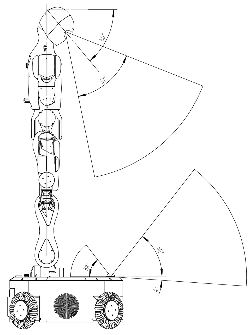
Head Camera and LiDAR Field of View
The Moz1 head camera defaults to a 50° angle with the horizontal direction. The field of view range is shown in the figure below. To adjust the head camera angle, refer to the section Head Angle Adjustment. The LiDAR is placed horizontally on the mobile platform, with the field of view range shown in the figure below.
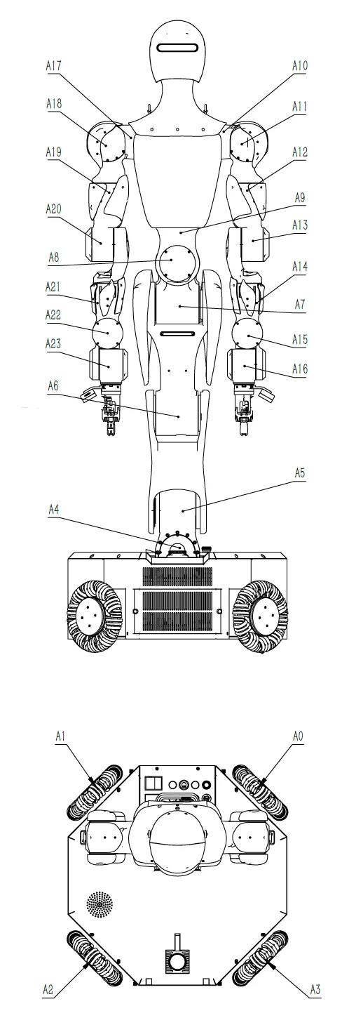
Working Range and Speed
The axis numbers, motion range, and speed limits for each Moz1 axis are as follows:
Head Angle Adjustment
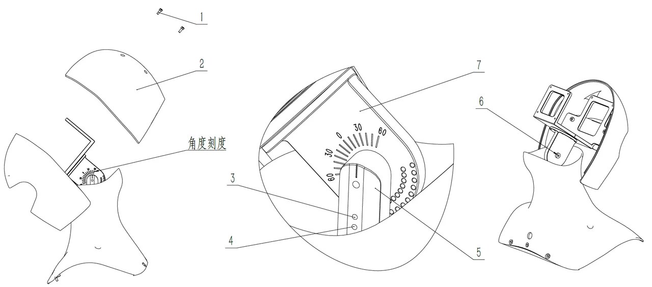
| No. | Name | Quantity | Function |
|---|---|---|---|
| 1 | Socket Head Cap Screw M3x8 | 4 | |
| 2 | Head Rear Shell | 1 | |
| 3 | Socket Set Screw M3x12 | 1 | 5°, 15°, 25°, 35°, 45°, 55° adjustment screw |
| 4 | Socket Set Screw M3x12 | 1 | 0°, 10°, 20°, 30°, 40°, 50°, 60° adjustment screw |
| 5 | Adjustment Bracket A | 1 | |
| 6 | Socket Shoulder Screw 5x15 | 1 | |
| 7 | Adjustment Bracket B | 1 |
The factory head angle is 50 degrees (as shown). To adjust the angle, follow these steps:
- Use an H2.5 hex wrench to remove 4 socket head cap screws M3x4, remove the head rear shell
- Use an H3 hex wrench to loosen the socket shoulder screw 5x15 by 1 turn
- Use an H1.5 hex wrench to loosen the socket set screw M3x12 to allow adjustment bracket B to rotate (loosen No. 3 or No. 4 depending on the angle before disassembly)
- Visually check the angle scale and rotate adjustment bracket B to the target scale position
- Use an H1.5 hex wrench to insert the socket set screw M3x12 (No. 3 or No. 4 depending on target angle) until adjustment bracket B cannot rotate freely
- Use an H3 hex wrench to tighten the socket shoulder screw 5x15
- Use an H1.5 hex wrench to tighten the socket set screw M3x12 (No. 3 or No. 4 depending on target angle)
- Install the head rear shell and use an H2.5 hex wrench to tighten 4 socket head cap screws M3x4 to complete angle adjustment
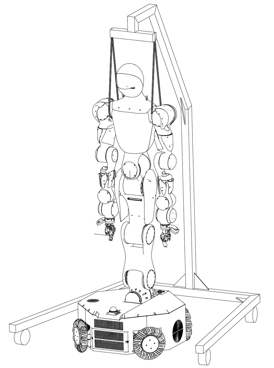
Hoisting Diagram
During robot maintenance or debugging, for the safety of the robot and users, it is recommended to use a hoist frame to protect the robot. The hoisting diagram is shown below:
Mobile Platform
Mobile Platform Overview
The mobile platform of this product is the core motion and control unit of the robot, integrating power drive, power management, AI inference, network communication, and safety control function modules. The mobile platform supports standard charging, network communication, and emergency safety control, suitable for autonomous mobile operations in various industrial and service scenarios.
Power Supply
Charging Interface (LP20 3-pin Flange Female Connector) (Interface 15)
The robot body's charging interface is located in the center of the right side of the mobile platform, adjacent to the bottom support plate, using an LP20 3-pin flange female connector format. It requires a Moz1 power cable with a dedicated plug for charging.
Usage Instructions:
- Please ensure the charging cable matches the power adapter and avoid using non-original accessories.
- Charging is a manual operation that requires the operator to connect on-site and confirm the connection status.
- Connecting or disconnecting the charging cable while the robot is running is strictly prohibited to prevent accidental triggering.
Charging Parameter Specifications
| No. | Parameter | Notes |
|---|---|---|
| 1 | Charging Parameters | 54.8V / 10A (constant current constant voltage) |
| 2 | Charging Method | Manual connection (requires manual operation) |
| 3 | Cycle Count | ≥1000 times (regular battery health checks recommended) |
| 4 | Comprehensive Battery Life | ≥1000 complete charge/discharge cycles |
DANGER
Notes:
- When charging, please confirm the robot is in "Stop" state with no external interference.
- If any abnormality occurs during charging (such as overheating, odor), immediately disconnect power and contact technical support.