Teleoperation and Data Collection
Device Connection
Device List
External control mode devices (hereinafter referred to as teleoperation) include Quest VR headset, VR controllers *2, and data cable connecting computer to robot motion control unit.
Software devices include MovaXHelper; note that Capture-X (data collection software) is not required for teleoperation only.
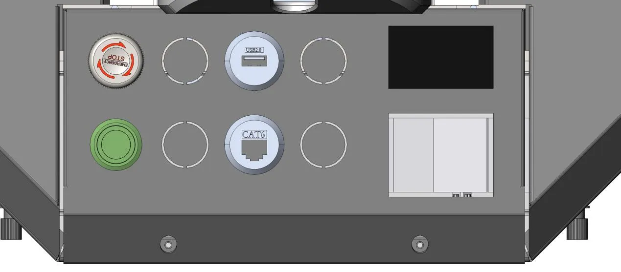
Connect the computer to the motion control unit (as shown below, CAT6 interface), connect the VR headset to the USB interface shown below, then turn on the VR device (power button is on the left side of the headset).
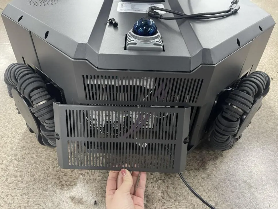
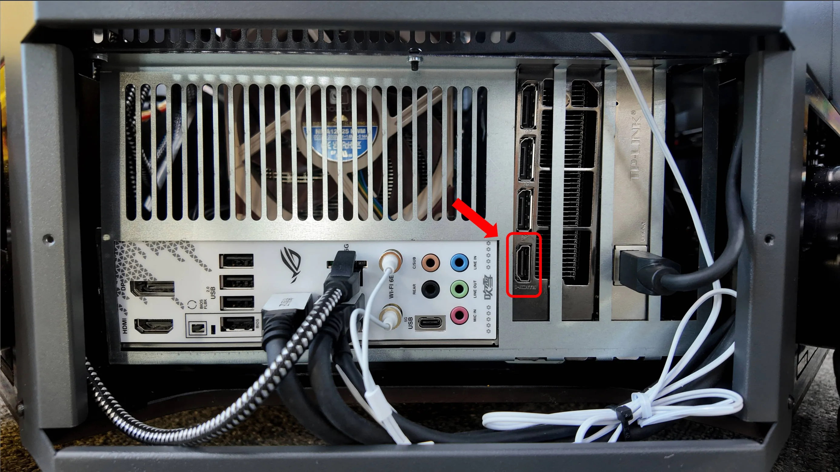
Open the external cover, connect the display (as shown in the two images below)
Device Startup and Connection
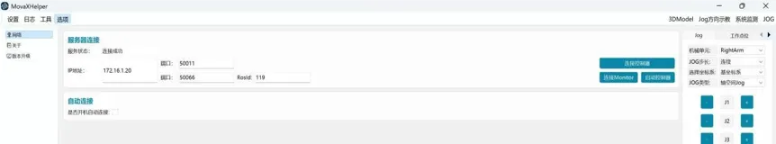
- Start MovaXHelper and enter 【Options】-【Network】 interface. Default wired connection IP address: 172.16.1.20; wireless connection through default assigned hotspot, hotspot name: Moz1-0900x (e.g., device 1 is Moz-09001).
RosId is set to 33 by default and must match the teleoperation configuration in step two's settings page. Also, enable 【Task Mode: External Control】 or 【Task Mode: User Control】 in the lower right corner.
 |
|---|
 |
|---|
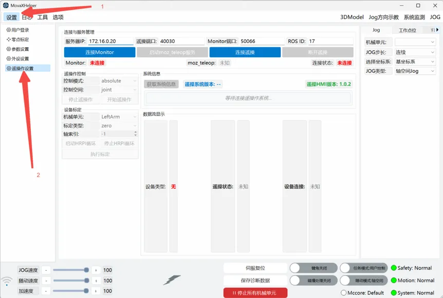
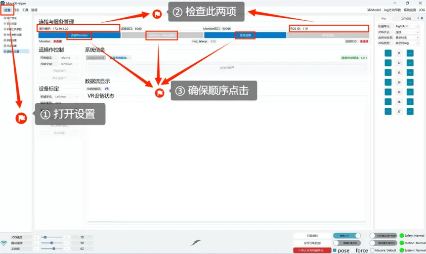
- Enter 【Settings】 page for teleoperation configuration.
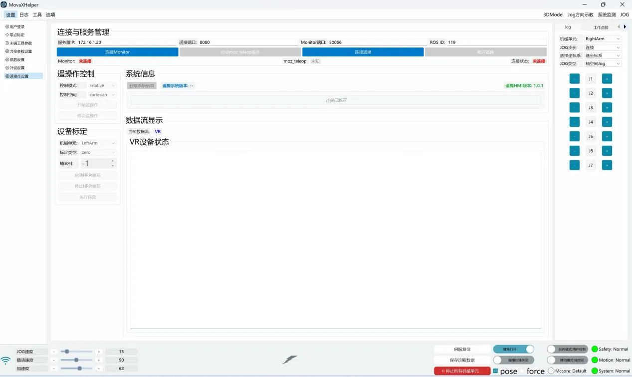
Check if Server IP and RosId settings match step one. Click in order from left to right: 【Connect Monitor】 ->【Start moz_teleop service】->【Connect Teleoperation】. Starting moz_teleop service may take about 10s depending on connection status.
 |
|---|
 |
|---|
After successful connection, status shows "Connected":
 |  |
|---|
INFO
Teleoperation HMI Version: 1.0.3 Update
Teleoperation function improves connection stability and page usability: added connection status information feedback on page 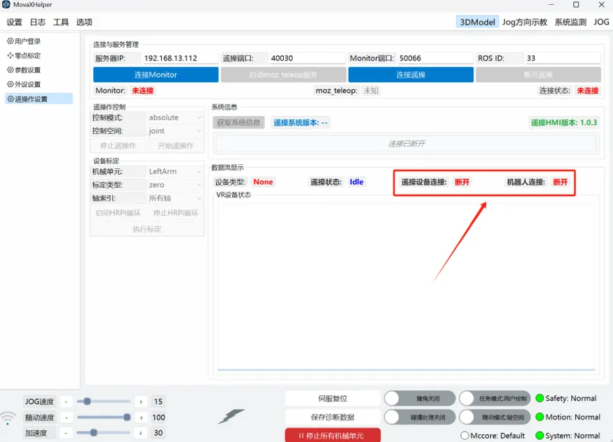
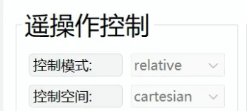
- (Default) Select Relative and Cartesian in teleoperation control bar
- Check VR device connection: After connecting teleoperation, VR headset defaults to green screen indicating successful startup.
After successful startup, press the VR left controller menu button to start teleoperation (see controller function key diagram below).
INFO
Controller Function Key Diagram
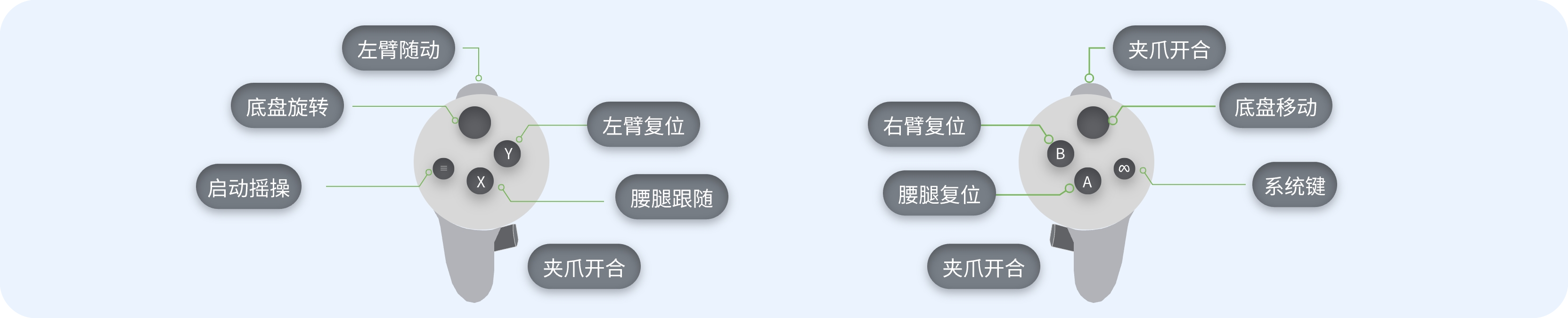
Left Controller:
- Menu key: Start teleoperation
- X key: Leg-waist follow key; long press this key, robot leg-waist follows headset movement, stops when released
- Y key: Left arm reset key, recommended to reset after each action is completed when surroundings are safe
- Left trigger: Left arm follow key, long press this key, left arm follows movement
- Left grip: Left gripper close key, grip to close, release to open
Right Controller:
- System key: Quest system key in VR page; system takeover, can enter VR page for debugging
- A key: Leg-waist reset key
- B key: Right arm reset key
- Right trigger: Right arm follow key, long press this key, right arm follows movement
- Right grip: Right gripper close key, grip to close, release to open
- Thumbstick: Base wheel forward/backward/left/right movement key
- Robot power on: Enter 【System Detection】 interface, select modules to power on, such as left arm, right arm, leg-waist.
DANGER
Note:  The lightning button below is quick power-on, not recommended for first-time operation.
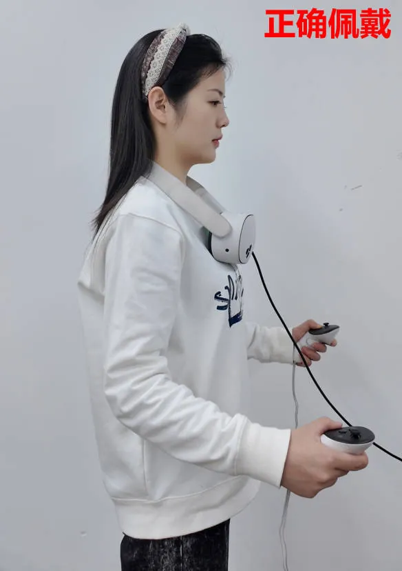
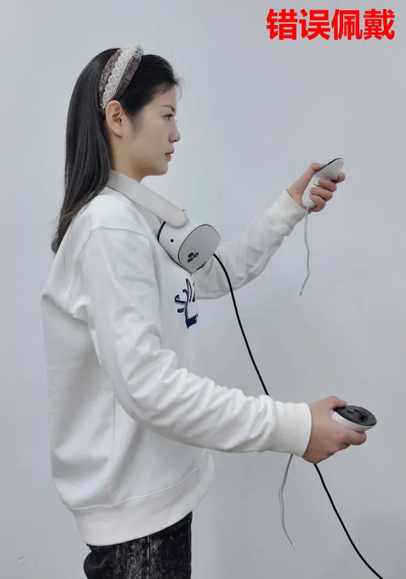
VR Wearing Demonstration
Correct wearing requires VR device perpendicular to head (Figure 1), incorrect wearing has VR device not perpendicular to head (Figure 2).
During teleoperation, controllers need to be below the headset (Figure 1), teleoperation will fail if above the headset (Figure 2).
| Figure 1 | Figure 2 |
|---|---|
 |  |
Safety Precautions
Reset is recommended after each teleoperation; check for obstacles at initial position before resetting.
User Login
Login
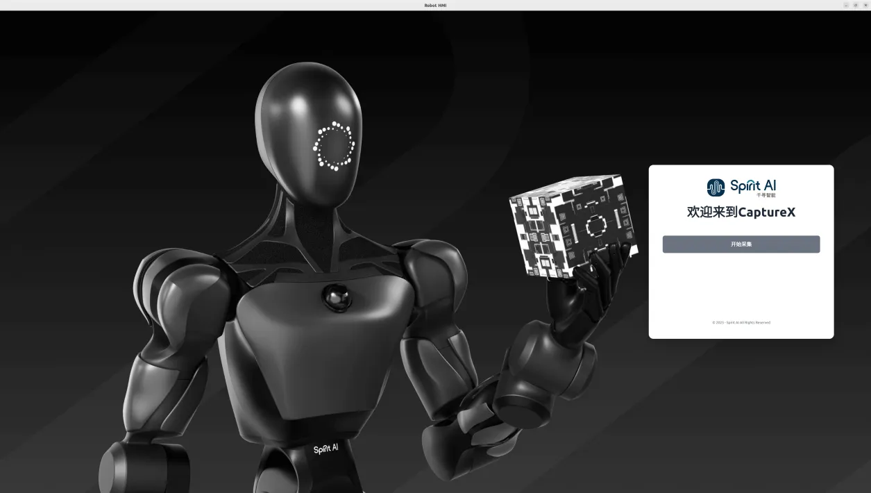
Enter HMI in command line to open data collection software
Login Interface
Click Start Collection to enter collection interface.
Data Collection System Functions
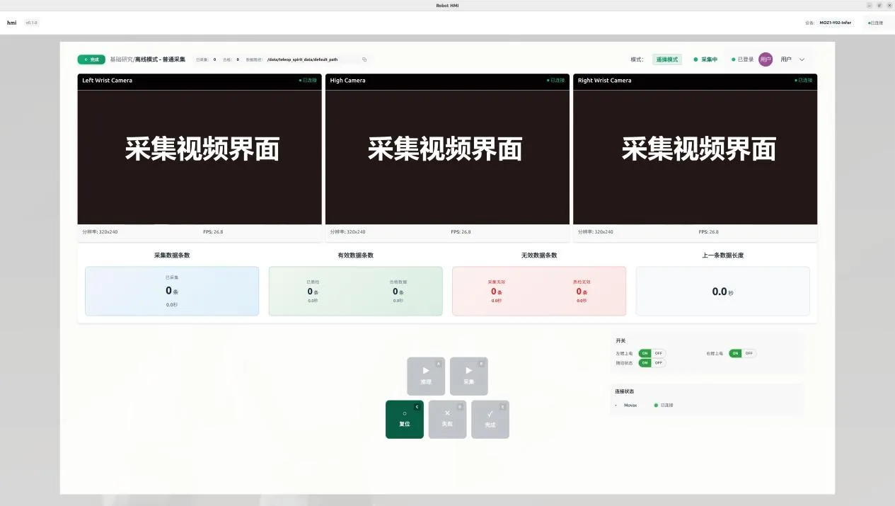
Status and Information Display
Device Model Information
Top right corner displays device model information, e.g., MOZ1-xyz.

Switch Status Bar
Switch status bar consists of three buttons controlling left arm power on/off, right arm power on/off, and follow status. Follow should be enabled during teleoperation; not recommended during inference (for safety); suggested to turn off all three switches at other times to prevent accidental teleoperation controller touches.

Connection Status Bar
Connection status bar displays MovaX connection status. 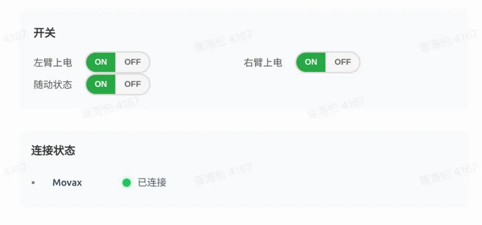
Data Collection Functions
Folder Path
Top left corner of interface shows default generated data path, supports copy function. Current version does not support modification. Complete button returns to login page.

Camera Windows
Shows top main camera and left/right hand secondary camera interfaces respectively. 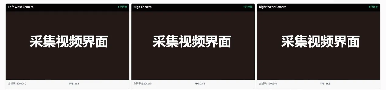
Data Information Bar and Operation Records
Shows collection count

Keyboard Function Area Buttons
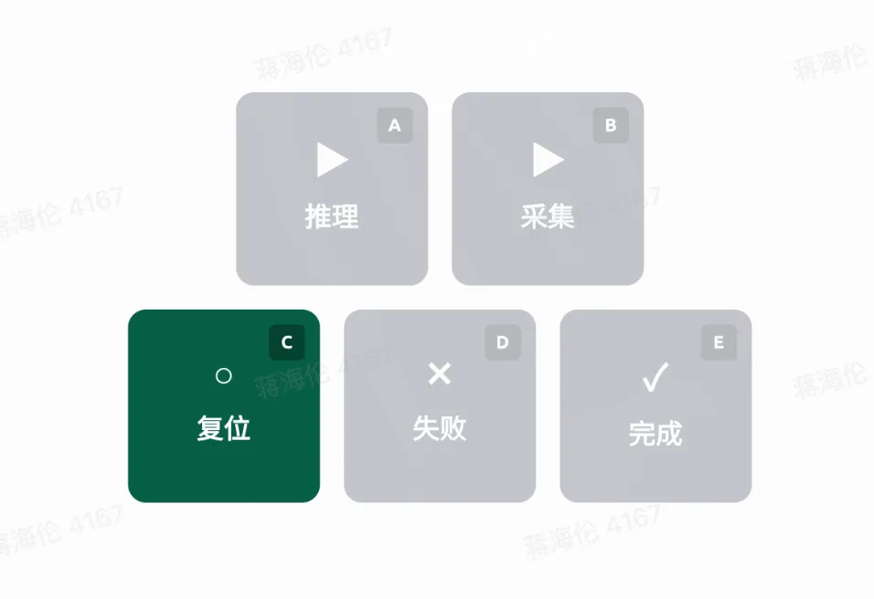
Function Pedal Labels
- Inference (corresponds to keyboard A key) -- Enable inference mode for deployed model. Note that inference and collection modes are mutually exclusive.
- Collect (corresponds to keyboard B key) -- Start single data collection.
- Reset (corresponds to keyboard C key) -- Robot returns to initial pose. Need to click reset first, then collect to ensure safety and data quality.
- Fail (corresponds to keyboard D key) -- Discard current data.
- Complete (corresponds to keyboard E key) -- Complete and record current data.