User Interface
DANGER
Note: Functions not explained in the documentation or involving parameter adjustments will affect robot operation. If you need to use them, please contact technical support. Do not adjust them without authorization.
MovaXHelper Software Introduction
MovaXHelper is the host computer software for the Mccore control system, with functions such as robot motion control, task editing, parameter settings, and status monitoring. This software can be installed on PC or tablet. As long as it is in the same network segment as the robot, it can control the robot by connecting to it.
HMI Overall Layout
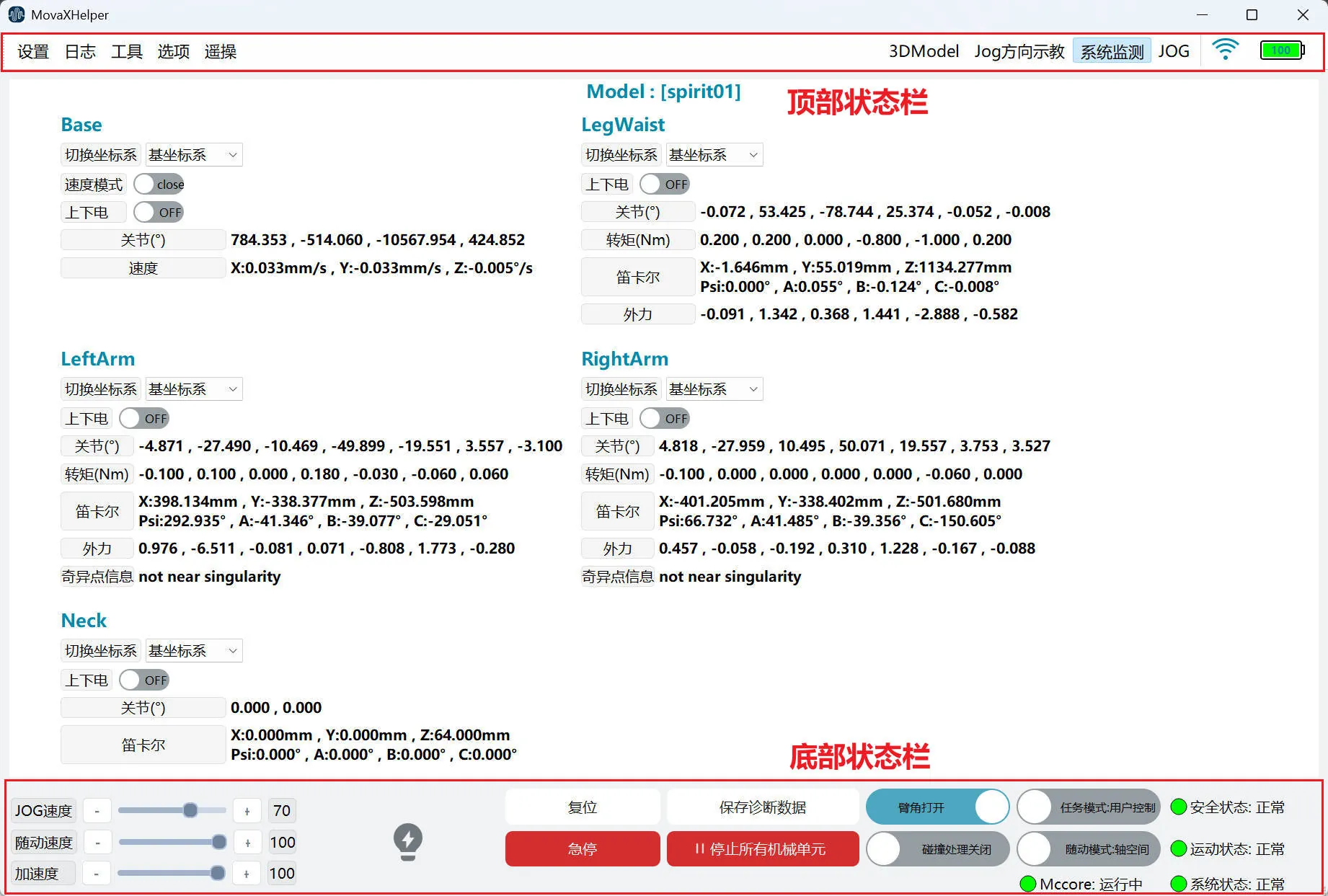 The main operation interface usually consists of 2 main areas, including: top status bar and bottom status bar.
Top Status Bar
The top status bar includes: several first-level menu buttons (Settings, Log, Options, Teleoperation), 3DModel button, Jog direction teaching button, System Monitoring button, JOG panel button, connection status, and battery display.
| Status Bar | Image Indicator | Description |
|---|---|---|
| Settings, Log, Options | 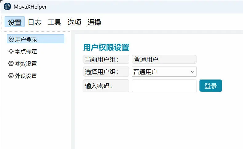 | First-level menu buttons, including Settings, Log, Options and other first-level menu buttons. Click to jump to the functional sub-interface. |
| 3DModel | 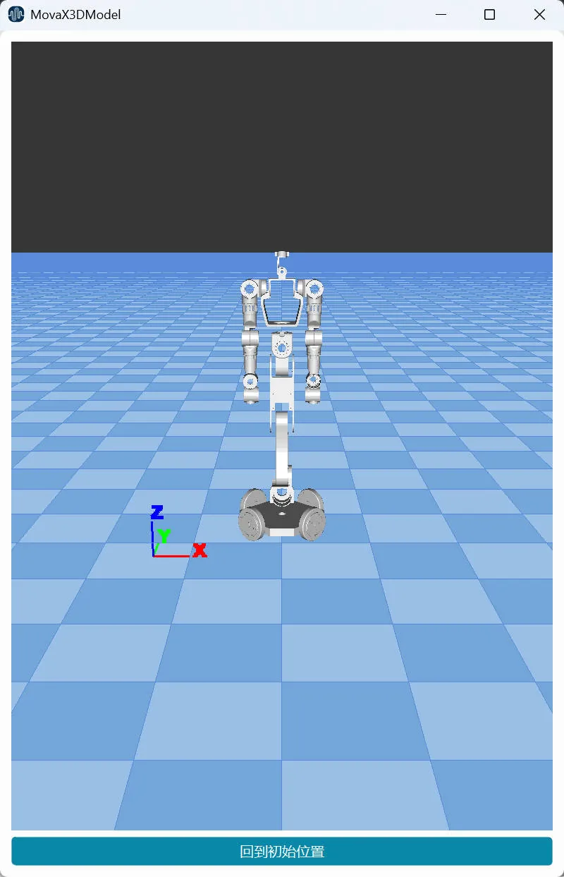 | 3D model display button. Click to open or close the display panel. This interface displays the current status of the robot in a three-dimensional model. The 3D model can be viewed from different angles by clicking and dragging, or you can click the "Return to Initial Position" button to return the model to the default viewing angle. |
| Jog Direction Teaching | 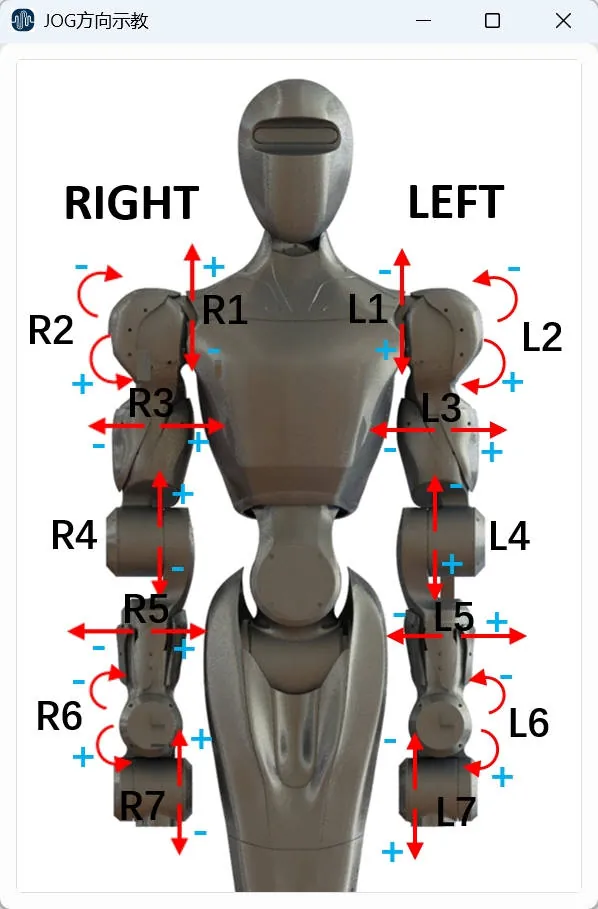 | Jog direction teaching display button, showing the "+" and "-" rotation directions of each joint to assist in Jog operation. Click to open or close the display panel. |
| System Monitoring | 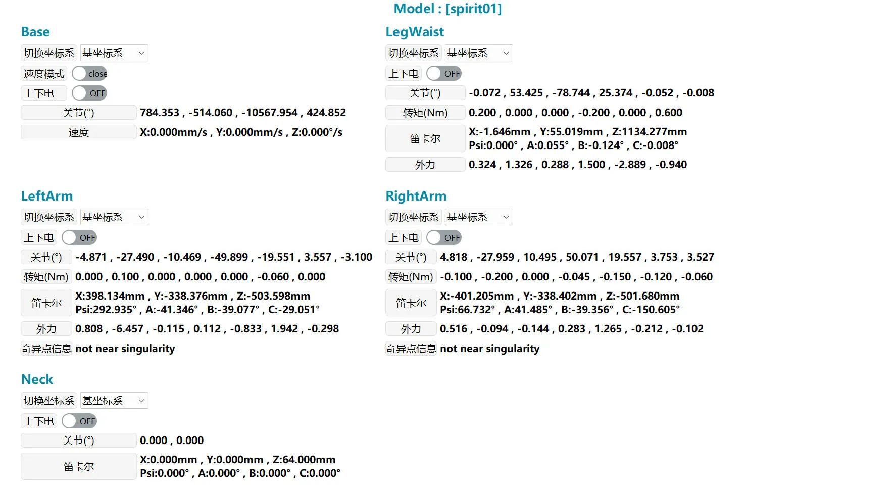 | System monitoring entry button, displaying the current power status, posture, force, and other states of the robot in real time. Click to open or close the control panel. |
| JOG Panel Button | 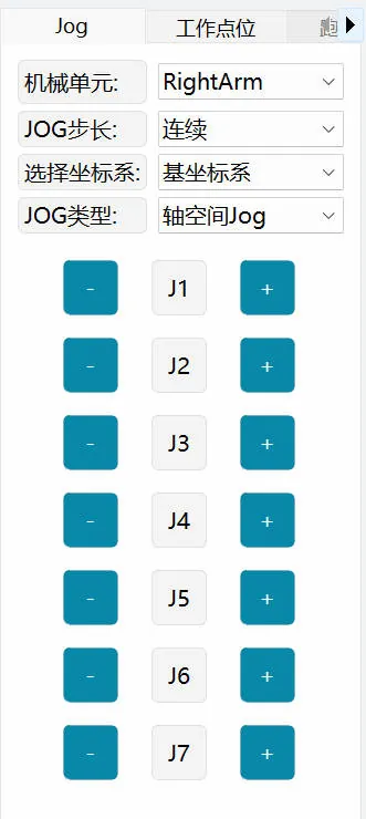 | JOG panel entry button. Click to open or close the control panel. |
| Connection and Robot Connection Status |  | Connection status between MovaXHelper software and the robot. Click this button to open the connection settings page with the robot. Icon showing full signal means connected; not full signal means not connected. When the controller service is not connected, the robot cannot be operated and robot parameters cannot be set. |
| Robot Battery Display |  | Robot battery display |
Left Sidebar
 When switching between different functions through the top status bar, such as Settings, Tools, etc., the left sidebar will display the corresponding sub-menus of the function.
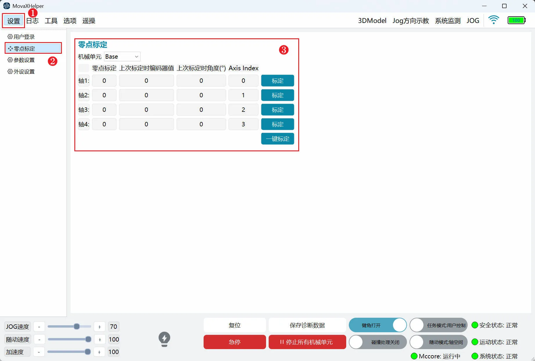
As shown in the figure above, click "Settings" in the top status bar, and the left sidebar displays all "Settings" sub-menus. Click "Zero Point Calibration" to enter the "Zero Point Calibration" settings page.
Right Control Panel
Click the JOG button in the top status bar to open the right control panel. The control panel is used to control the robot's movement, automatic calibration, etc.
| Status Bar | Image Indicator | Description |
|---|---|---|
| Jog | 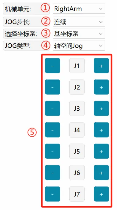 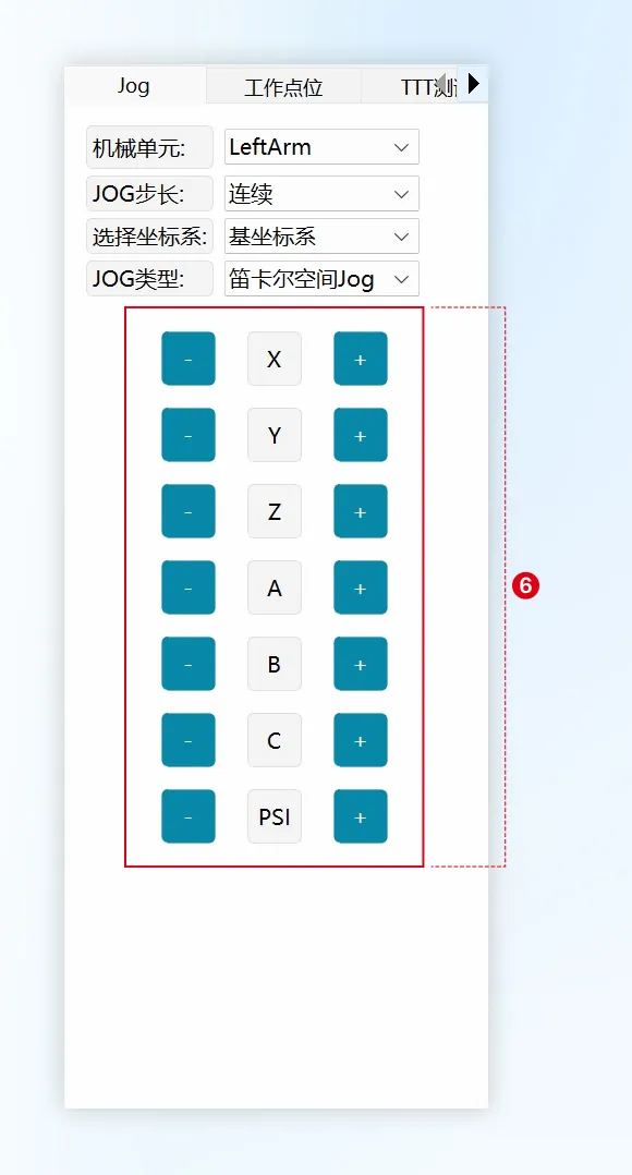 | ① Mechanical Unit: Select the mechanical unit to Jog, including LeftArm, RightArm, LegWaist and Base (mobile platform). ② JOG Step Size: You can choose continuous Jog or incremental Jog, and adjust the size of the incremental step. ③ Select Coordinate System: Used to select the reference coordinate system in Cartesian mode, including: base coordinate system and mobile platform base coordinate system. ④ JOG Type: Used to select single-axis mode and Cartesian mode during Jog. ⑤ Axis Space Jog Buttons: Displays J1~J6/J7 during axis space Jog (depending on the mechanical unit selected in ①). ⑥ Cartesian Space Jog Buttons: Displays X/Y/Z/A/B/C and PSI during Cartesian space Jog. |
| Jog-Mobile Platform | 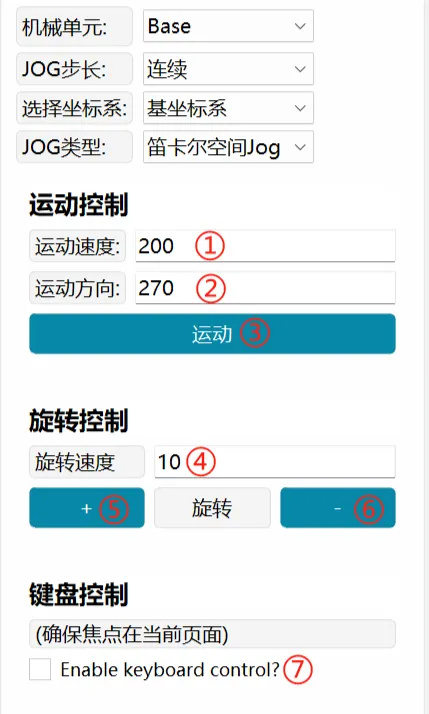 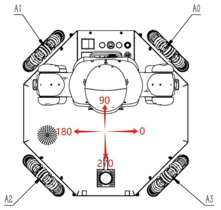 | The mobile platform running speed rate is adjusted in "Settings-Parameter Settings", with an adjustment range of 1-100%, which is a percentage relative to the speed limits of ② and ④. Mobile platform JOG only supports Cartesian mode. Motion Control: Controls the mobile platform to run in a straight line in different directions. ① Motion Speed: Effective range 0-500, unit: mm/s ② Motion Direction: Effective range 0-360, corresponding to the motion direction as shown in the left diagram. ③ Motion: Click the button, the mobile platform starts to run, and stops when released. Rotation Control: Controls the mobile platform to rotate in "+" and "-" directions ④ Rotation Speed: Effective range 0-60, unit: °/s ⑤ +: Mobile platform rotates in the direction of "0-90-180-270-0" ⑥ -: Mobile platform rotates in the direction of "0-270-180-90-0" Keyboard Control: Use keyboard "↑""↓""←""→" keys to control mobile platform movement ⑦ Enable keyboard control?: Check this item to control the mobile platform through the keyboard: ↑: Runs in a straight line in the same direction as entered in ② ↓: Runs in a straight line in the opposite direction as entered in ② ←: Mobile platform rotates in the direction of "0-90-180-270-0" →: Mobile platform rotates in the direction of "0-270-180-90-0" When using the keyboard, the mouse focus must be kept on the current page. |
| Work Points | 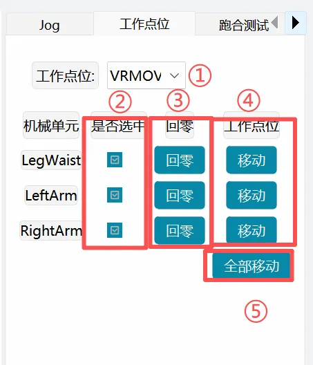 | ① Work Point: Select an established work point ② Select Mechanical Unit: Select the mechanical unit to move ③ Return to Zero: Single mechanical unit each axis returns to zero point ④ Single Mechanical Unit Movement: Single mechanical unit moves to the work point selected in ① ⑤ Move All: Mechanical units selected in ② move to the work point selected in ① |
| Running-in Test | 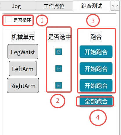 | ① Loop or Not: Check this item to run the running-in points in a loop ② Select Mechanical Unit: Select the mechanical unit to run ③ Single Mechanical Unit Run: Single mechanical unit runs ④ All TTTT: Mechanical units selected in ② run |
| Auto Calibration | 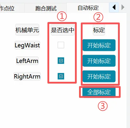 | ① Select Mechanical Unit: Select the mechanical unit to calibrate. Dual arms and leg-waist cannot be selected simultaneously ② Single Mechanical Unit Calibration: Single mechanical unit calibration ③ Calibrate All: Calibrate mechanical units selected in ①. Dual arms and leg-waist cannot be selected simultaneously |
Bottom Status Bar

| No. | Description | |
|---|---|---|
| ① | 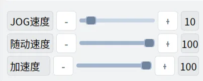 | Running speed adjustment control, used to adjust the running speed of dual arms and leg-waist. Adjustable range is 1%~100%. JOG speed and following speed independently affect the running speed of user control and external control modes respectively. Acceleration is common to both modes. Click the slider or -/+ buttons to fine-tune the program speed (-/+1%). |
| ② |  | All mechanical unit motors are in powered-off state. Click to power on all mechanical units. |
 | Some mechanical unit motors are powered on. Click to power off all mechanical units. | |
 | All mechanical unit motors are powered on. Click to power off all mechanical units. | |
| ③ |  | Servo reset button. When the robot is in emergency stop or servo error state, after eliminating the factors causing the above states, click this button to restore the robot state. |
| ④ |  | Emergency stop button |
| ⑤ |  | Manually save diagnostic data from the last 60 seconds. |
| ⑥ |  | In user control mode, after clicking, all mechanical units stop running but remain powered. |
| ⑦ |  | Arm angle switch, enabled by default; recommended to turn on during external control. |
| ⑧ | 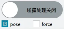 | This function only takes effect when collision detection occurs. You can choose pose or force mode to clear the collision alarm. |
| ⑨ |  | User control mode, can operate the robot through HMI, gamepad, etc. |
| ⑩ |  | External control mode, cannot operate the robot through HMI, gamepad, etc. |
| ⑪ |  | Current controller safety status: green indicates safe status; red indicates unsafe status. |
| ⑫ |  | Current robot running status: green indicates idle status; red indicates busy status, robot is in motion. |
| ⑬ |  | Current control system status: green indicates normal motion status; red indicates system abnormality. |
| ⑭ |  | Program running status, obtained after connecting to monitor. |
| ⑮ |  | Program running normally. If red, it means the program has not started normally. Click to start the controller and wait for the program to run. |
System Monitoring
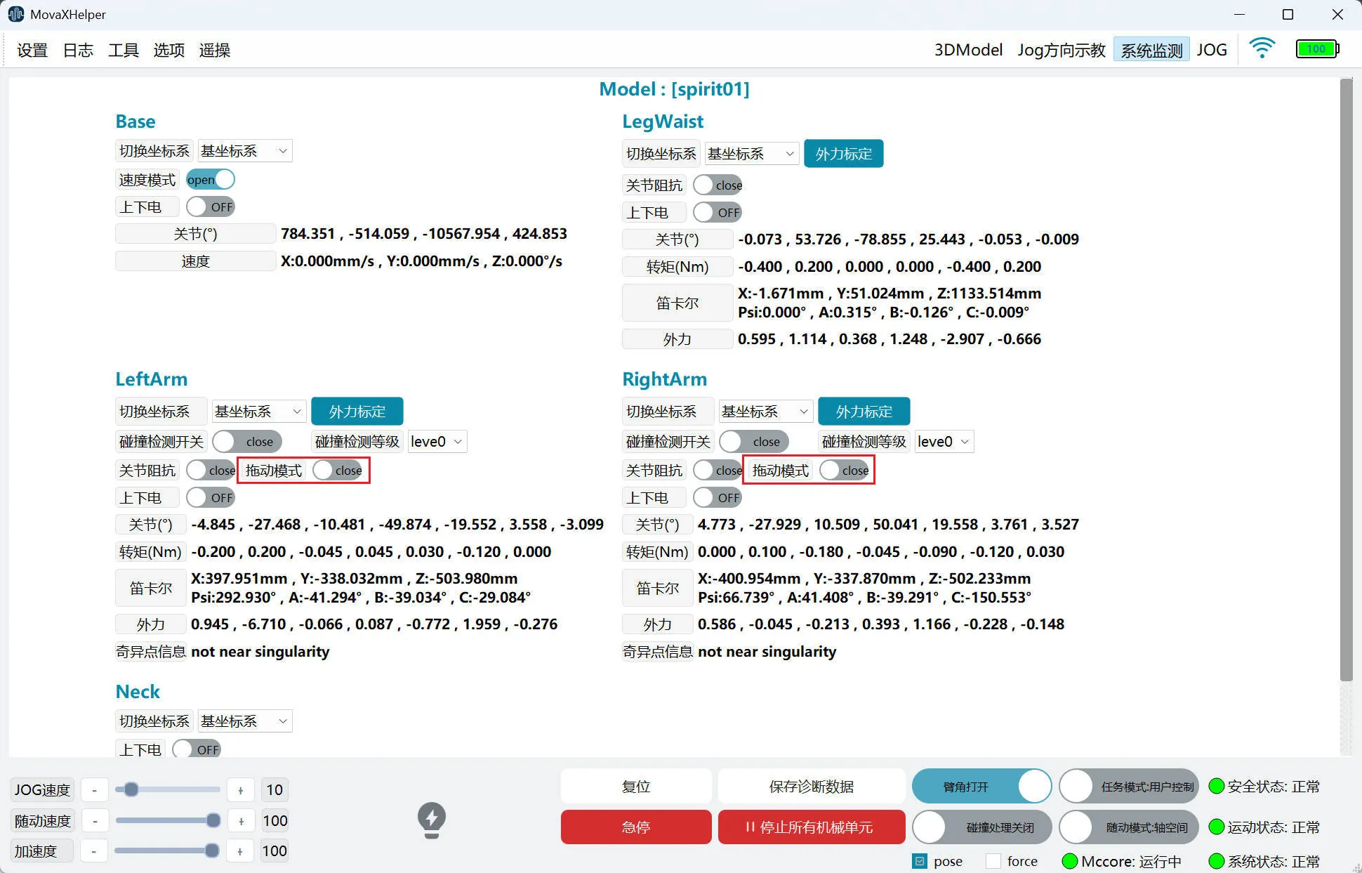
Click the "System Monitoring" button in the status of the top status bar to open the status monitoring panel. Through the status monitoring panel, you can monitor: the current angle, torque, Cartesian posture, external force situation and singularity information of each joint of the robot, making it easy for users to quickly understand the robot status. 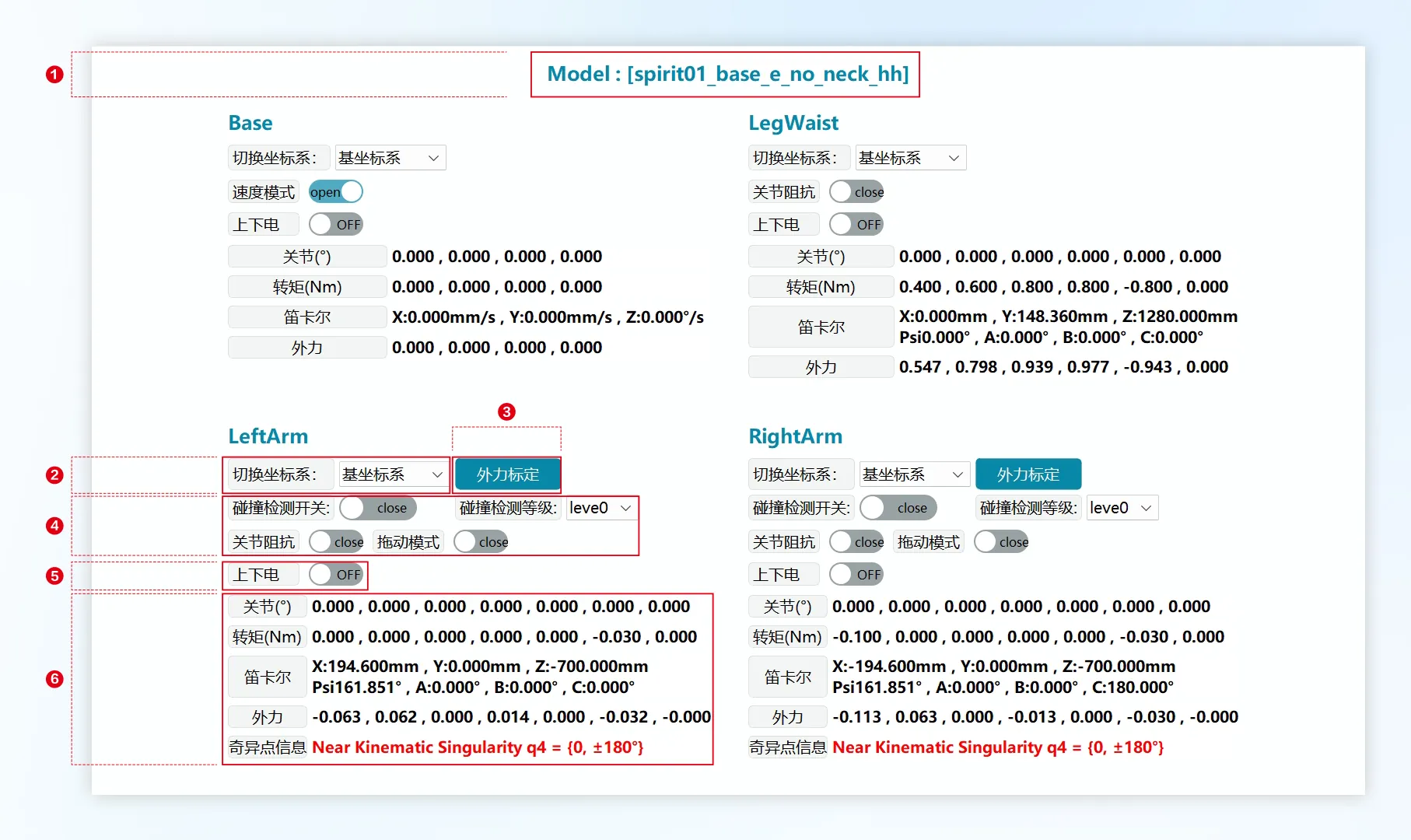
| No. | Description |
|---|---|
| ① | Model: The model currently used by the robot. |
| ② | Switch Coordinate System: You can choose base coordinate system or mobile platform base coordinate system. The Cartesian readings in ⑥ will change accordingly. |
| ③ | External Force Calibration: Perform external force calibration when the mechanical unit is in zero point posture. |
| ④ | Force control related functions. |
| ⑤ | Power On/Off: Single mechanical unit power on/off switch. |
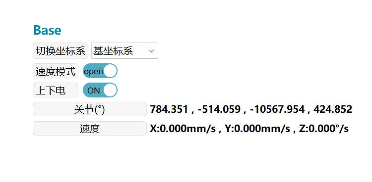
| ⑥ | Joints: Current axis angle of each axis of the mechanical unit. Torque: Current torque of each axis of the mechanical unit. Cartesian: Position and posture of the mechanical unit end effector relative to the current coordinate system. External Force: Current external force situation of each axis of the mechanical unit. Singularity Information: When the robot is near a singularity, red warning is displayed. At this time, Cartesian space motion may be affected, and the speed of some joints may be very fast, which may cause errors and the robot operation to stop. |
Power On/Off
Users can power on/off a single mechanical unit through the power on/off switch on the "System Monitoring" page, or control the power on/off of all mechanical units through the button in the bottom status bar.
System Monitoring
| Status Indicator | Description |
|---|---|
 | The mechanical unit is currently powered off. Click to power on the mechanical unit. |
 | The mechanical unit is currently powered on. Click to power off the mechanical unit. |
 | The mechanical unit is currently in an abnormal powered-off state. The abnormal situation must be cleared before normal power on/off can occur. |
Bottom Status Bar
| Status Indicator | Description |
|---|---|
 | All mechanical unit motors are powered off. Click to power on all mechanical units. |
 | Some mechanical unit motors are powered on. Click to power off all mechanical units. |
 | All mechanical unit motors are powered on. Click to power off all mechanical units. |
Motion Control
JOG Jogging
Please first read MovaXHelper Software Introduction about interface function button settings.
Mechanical unit Jog jogging supports two modes: axis space and Cartesian space:
Axis Space: Control individual axis motion. For motion directions, refer to "JOG Direction Teaching".
Cartesian Space: Control the mechanical unit to move in a given coordinate system direction individually. For example, if you select "Base Coordinate System" and Jog X, it will translate along the X direction of the base coordinate system; if you select "Mobile Platform Base Coordinate System" and Jog B, it will rotate along the Y direction of the mobile platform base coordinate system. For motion directions, refer to "3DModel".
INFO
For safety reasons, coordinate system selection permission is temporarily not open to users. When JOGing, the controller's default coordinate system is used.
Jog jogging supports continuous and incremental modes:
In continuous motion mode, after the robot is powered on, hold down the Jog button, and the robot moves continuously at the set Jog speed until the enable or Jog button is released.
In incremental step mode, after the robot is powered on, each press of the Jog button moves the robot by a given step size. Users can select an appropriate step size as needed, mainly used to precisely adjust the robot's posture.

Jog Speed Setting: Control the robot's motion speed during Jog through the speed setting space in the mobile platform status bar. Selectable range is 1%~100%. At 100%, it corresponds to the robot's maximum TCP speed of 250mm/s. Due to safety regulations, for both Cartesian space Jog and axis space Jog, TCP linear velocity will not exceed 250mm/s.
Mobile Platform JOG
When JOGing the mobile platform, you need to first turn on the "Speed Mode" switch on the "System Monitoring" page and then power on.
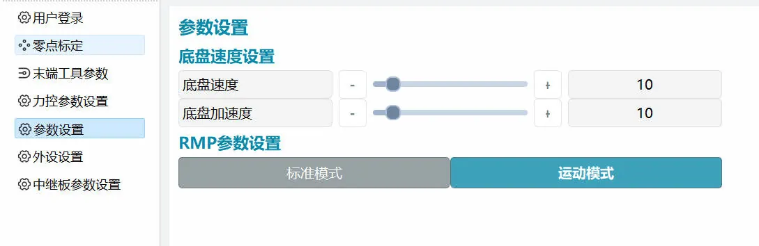
The running speed of the mobile platform is set through the "Settings-Parameter Settings" page, with an adjustment range of 1~100%, which is a percentage relative to the mobile platform's "Motion Speed" and "Rotation Speed" on the JOG page.
Neck Joint JOG
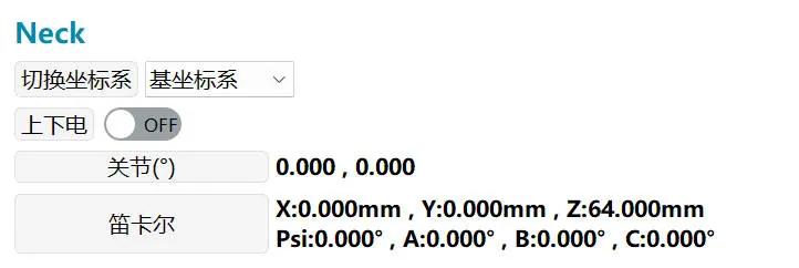 | 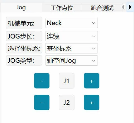 |
Neck joint JOG control method: J1 is left-right rotation, J2 is up-down pitch
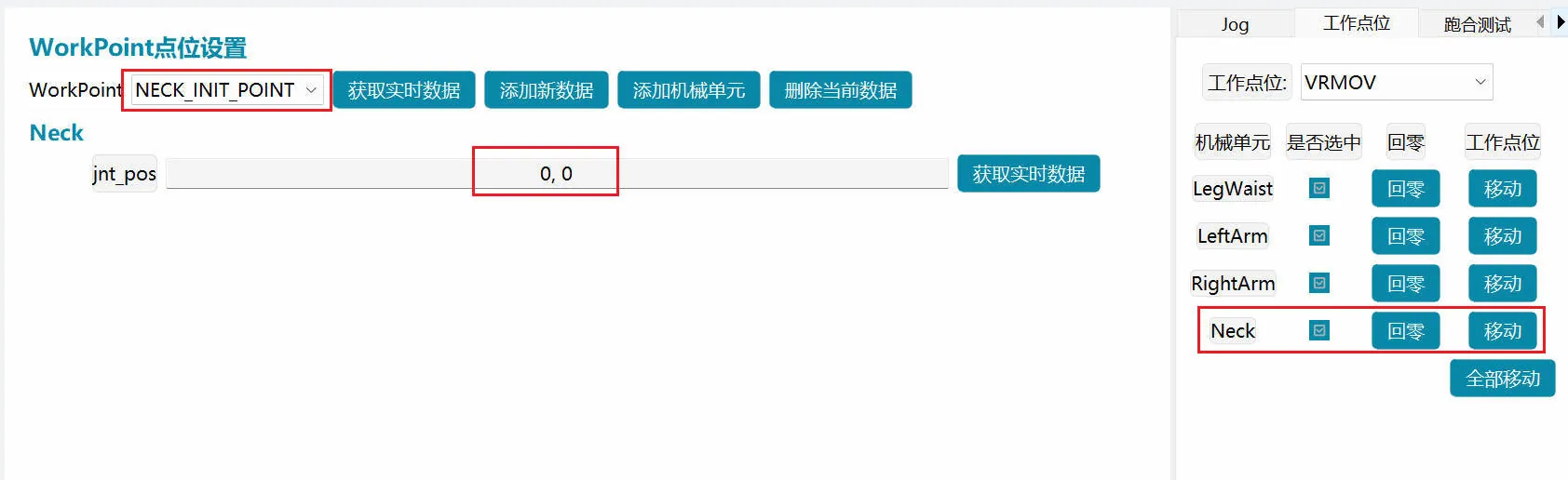 Work point setting and operation (left-right maximum limit values are ±65, pitch maximum limit values are -3, 50)
TIP
Note: jit_pos: This parameter can be set to the required posture, and after the next power-on, it will run to the set posture position
Work Points
The "Work Points" on the right control panel of HMI provides a quick posture adjustment function. Users can enter the "Set Work Points" page through "Tools" in the top status bar to set commonly used postures as work points. 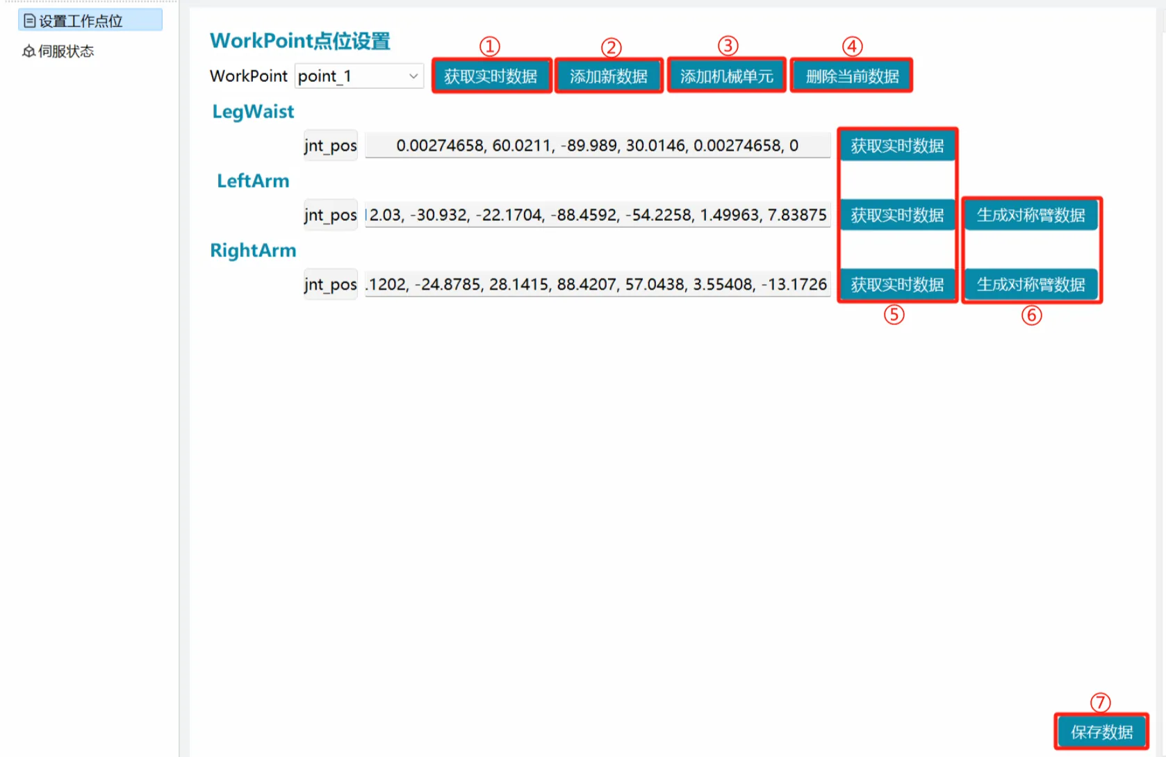
- ① Get Real-time Data: Get the current angle values of all mechanical units and update to the selected point.
- ② Add New Data: Add a new work point.
- ③ Add Mechanical Unit: Add a mechanical unit (currently only supports adding dual arms + leg-waist, does not support mobile platform).
- ④ Delete Current Data: Delete the currently selected work point.
- ⑤ Get Real-time Data: Get the current angle value of a single mechanical unit and update to the mechanical unit selected for this point.
- ⑥ Generate Symmetric Arm Data: Left and right arms generate symmetric data from each other.
- ⑦ Save Data: Save operations on this point.
For example, click ② "Add New Data", a pop-up window appears to name the new point (names cannot be duplicated). Jog the mechanical unit to the required point, click ① / ⑤ "Get Real-time Data", click ⑦ "Save Data". The "Work Points" in the right operation panel can then select this point. After ④ "Delete Current Data", you also need to ⑦ "Save Data" to delete normally.
The "Work Points" usage is similar to Jog operation. Power on the mechanical unit, press the corresponding target posture "Move" button, and the mechanical unit will move to the target posture through axis space. You can also power on all mechanical units and use "Move All" to make all mechanical units move to the target posture simultaneously.
The speed during motion can be adjusted through Jog speed.
Among them, Home (common initial posture) and Docking (shipping posture) are bound to the gamepad. Users can adjust the point angle values according to actual situations. If not set, the default configuration is used.
DANGER
When there is a large difference between the robot's current posture and the target posture, there is a collision risk between mechanical units during the "Move All" process. It is recommended to adjust each mechanical unit sequentially.
Running-in Test
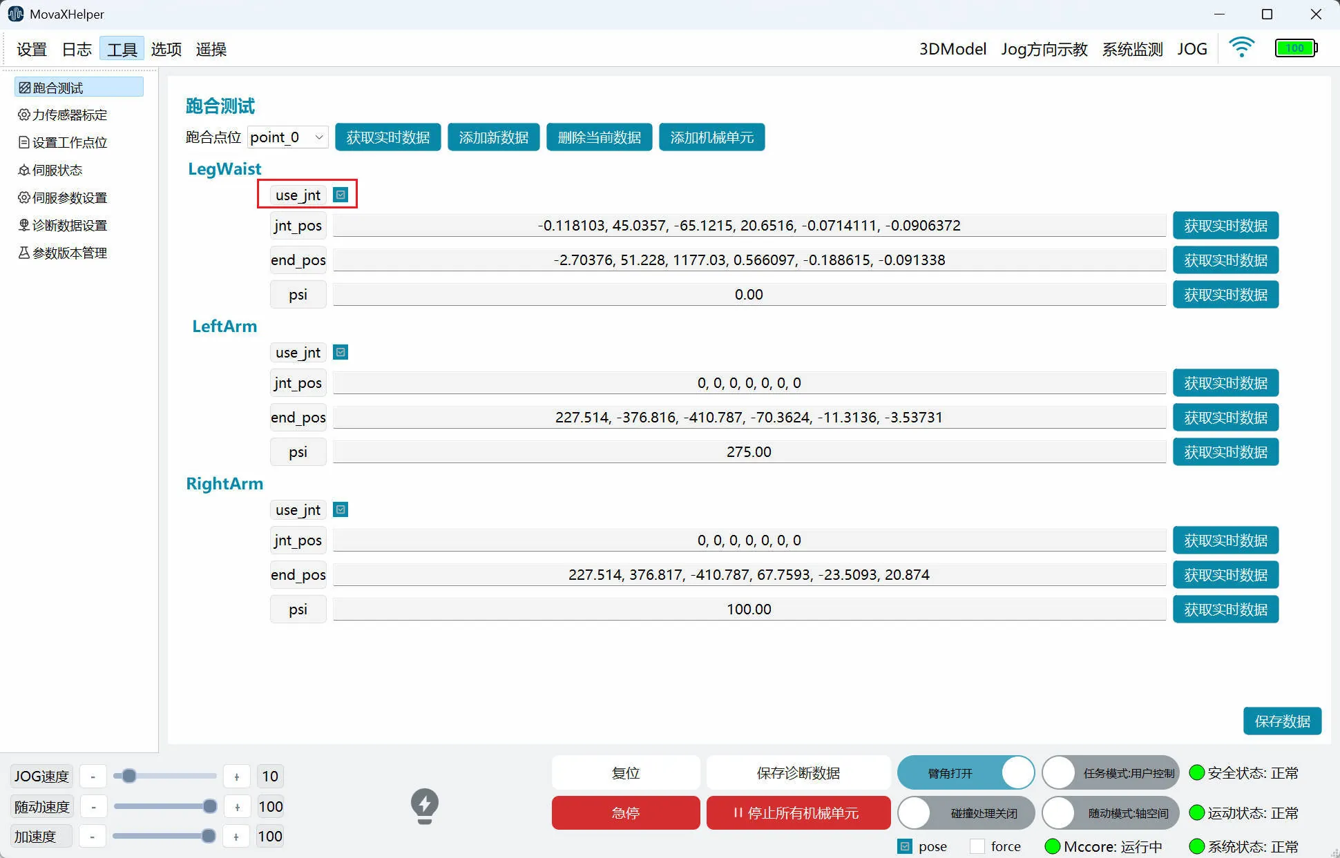
Users can add multiple points through the "Running-in Test" page. The method is basically the same as "Work Points", except that after clicking "Save Data", the controller needs to be restarted to take effect.
It should be noted that "Work Points" only supports axis space motion, while "Running-in Test" supports both axis space and Cartesian space, distinguished by "use_jnt". When this item is not checked, the mechanical unit moves from the previous point to the current point through Cartesian space motion; if checked, it moves through axis space.
Force Control Functions
Joint Impedance
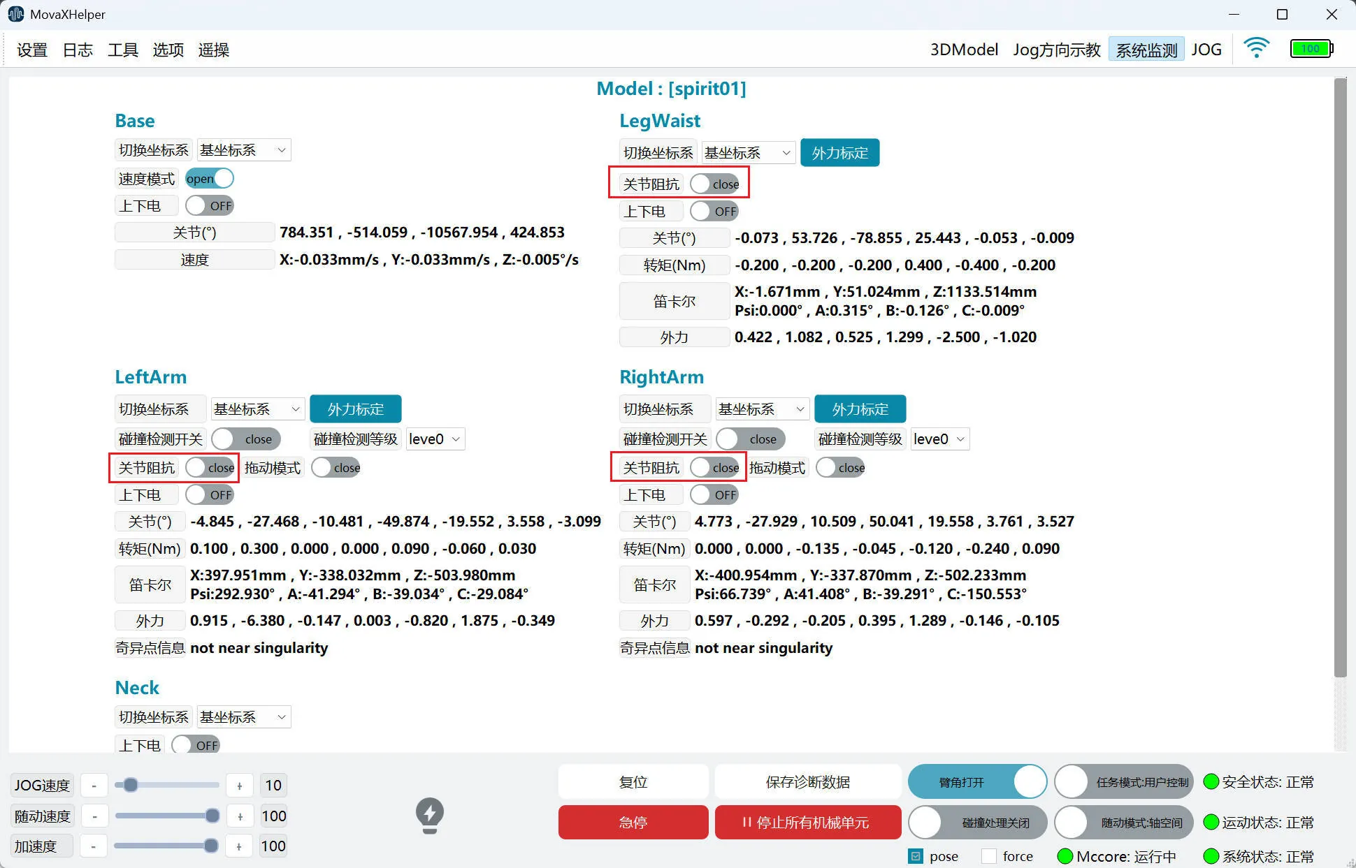 After enabling joint impedance, the mechanical unit will exhibit characteristics similar to a damped spring, allowing the robotic arm to have a certain degree of compliance when interacting with the external environment.
The joint impedance function is enabled on the "System Monitoring" page. When enabling, the mechanical unit must be in a powered-off state. The function takes effect after powering on.
- This function does not support simultaneous use with drag mode; it supports simultaneous use with collision detection.
- This function supports both user control mode and external control mode.
- It takes effect in both static and running states.
Drag Mode
 When drag mode is enabled, the mechanical unit enters "zero force space", and users can manually guide the mechanical unit's joints to the required position and posture.
Drag mode is enabled on the "System Monitoring" page. When enabling, the mechanical unit must be in a powered-off state. The function takes effect after powering on.
- Currently only supports dual arms.
- This function does not support simultaneous use with joint impedance; does not support simultaneous use with collision detection.
- This function only supports user control mode.
- When in drag mode, "Jog", "Work Points", "TTT Test", and "Auto Calibration" functions cannot be used.
When drag mode is enabled, the virtual wall is enabled by default. The virtual wall limits each joint's workspace in robot dragging scenarios to protect the robot. When a dragged joint approaches the virtual wall, users will feel the reaction force from the virtual wall.
The virtual wall boundary for each joint is within 5° of its soft limit. For example, if the joint soft limit is -180° to +180°, in drag mode the joint operates within -175° to +175°.
WARNING
Before enabling drag mode, the robot's dynamics parameters and load parameters must be accurately set, otherwise there may be a drifting feeling during dragging. Under extreme conditions of excessive drag force or speed, the robot may exceed the virtual wall range, causing an error state.
Collision Detection
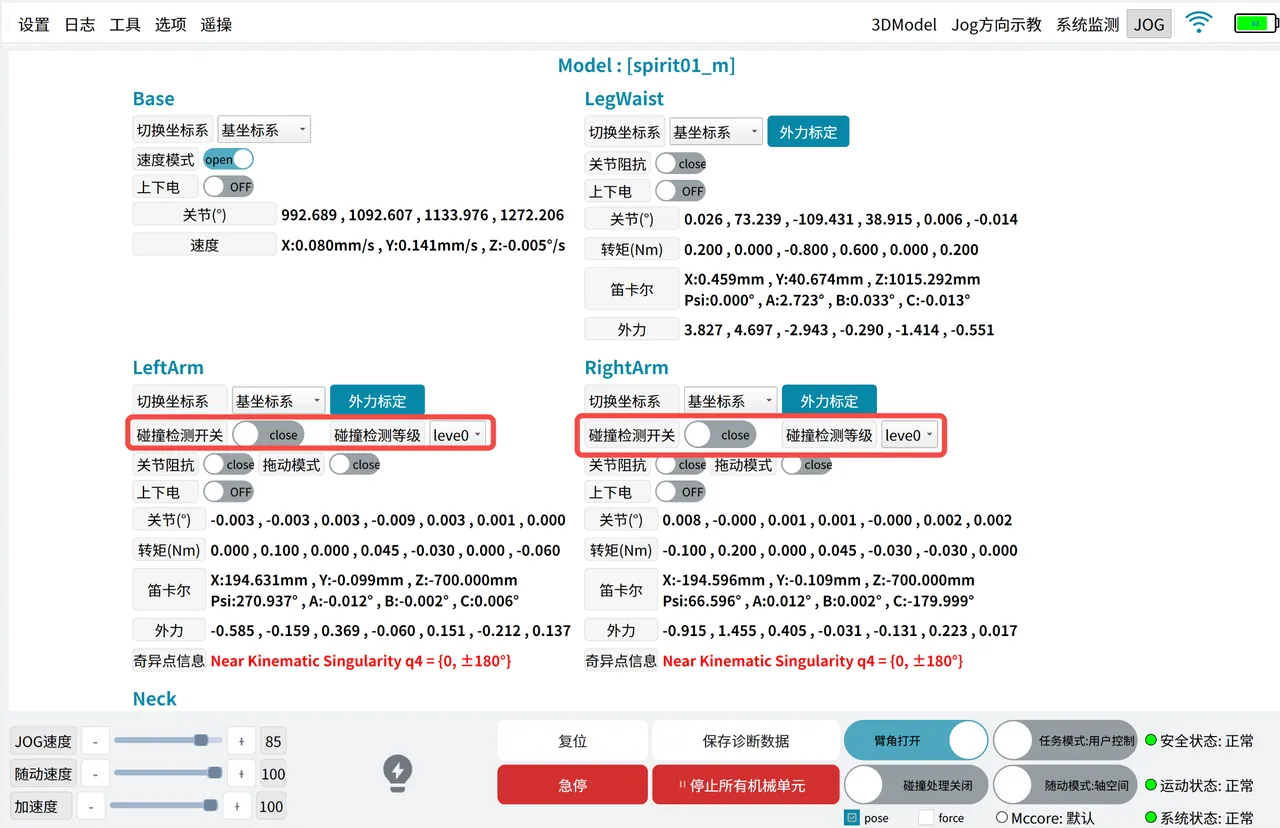
Collision detection is a passive detection function based on the robot's dynamics model estimation. When the robot collides unexpectedly with the external environment while stationary or running, collision detection can detect the collision in time and execute pre-set handling measures.
The collision detection function is enabled on the "System Monitoring" page. Enabling is not restricted by the mechanical unit's state. The function takes effect after powering on.
There are 8 collision detection levels. The lower the level, the higher the sensitivity, and the easier it is for the robot to detect collisions.
- Currently only supports dual arms.
- This function does not support simultaneous use with drag mode; supports simultaneous use with joint impedance.
- This function supports both user control mode and external control mode.
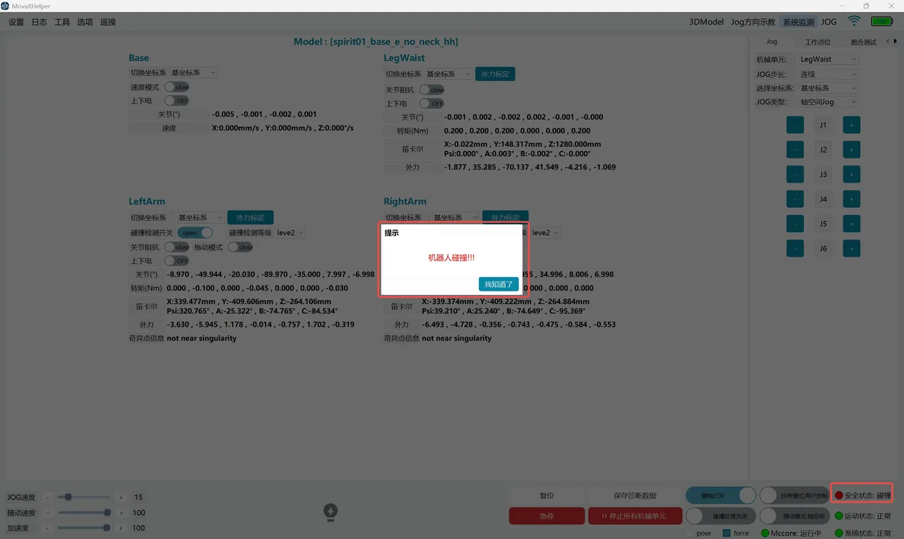
After triggering collision detection, the robot will immediately stop and power off. A pop-up window will prompt on the interface, and the "Safety Status" indicator in the bottom status bar will turn red and display "Collision". At this time, the robot is in an abnormal state and cannot be powered on. It needs to be recovered through the "Collision Handling" function before continuing to use.
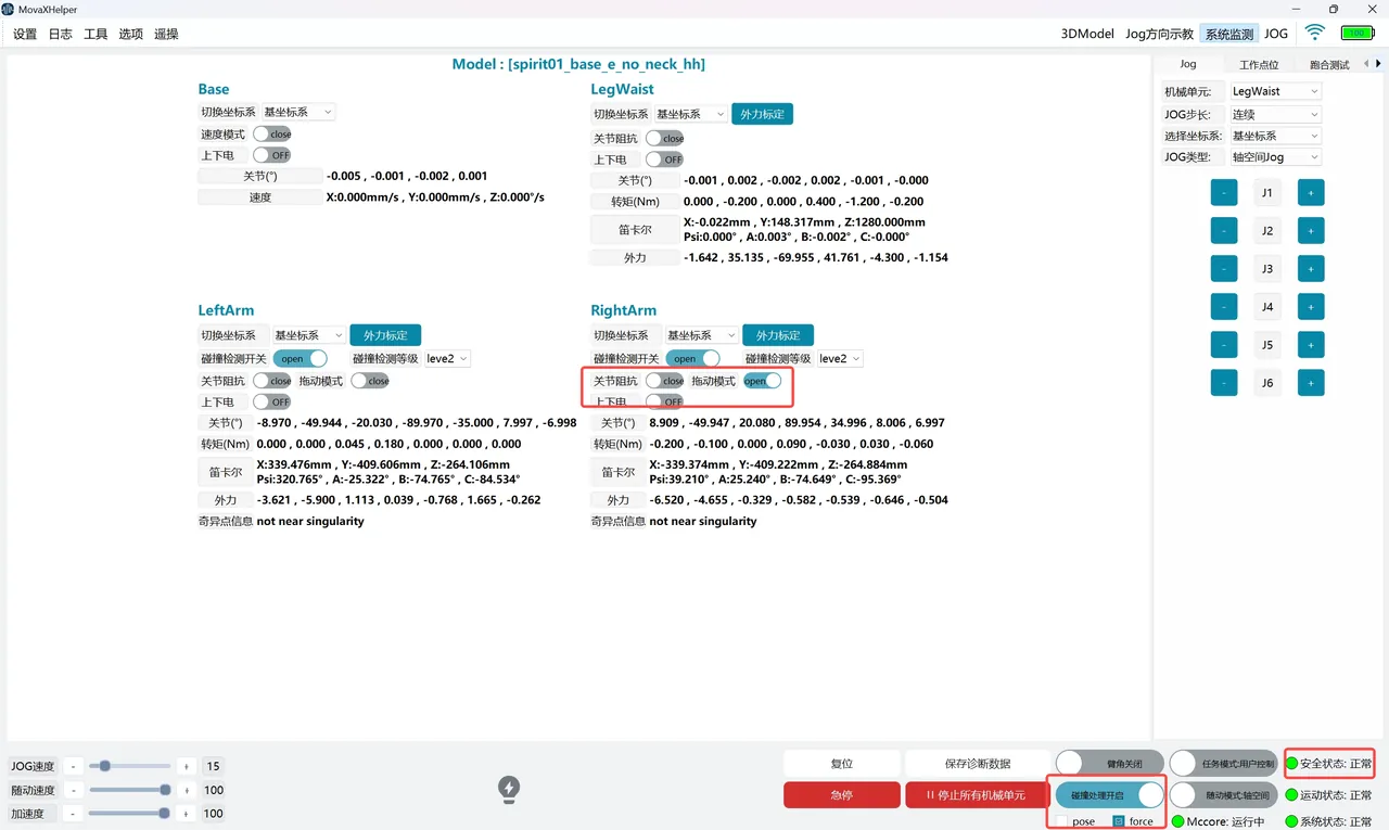
The "Collision Handling Enable" switch is only enabled when a collision is detected. Before enabling, you need to select a handling mode according to the collision scenario. Currently, "pose" and "force" modes are supported.
- "pose" mode: In this mode, use manual Jog to move the collided mechanical unit to a safe area;
- "force" mode: In this mode, move the collided mechanical unit to a safe area by manual dragging; Taking "force" mode as an example, the collision handling operation steps are as follows:
- Select "force" mode, turn on the "Collision Handling Enable" switch, the "Safety Status" indicator recovers to green and displays "Normal"; but the collision state has not recovered at this time. If the "Collision Handling Enable" switch is turned off, it will return to "Collision".
- Hold the handheld emergency stop, turn on the "Drag Mode" switch for the collided mechanical unit and power on; if the mechanical unit has been in contact with the collision object before, the mechanical unit will move a distance away from the object after powering on until it is no longer in contact with the collision object;
- Manually drag the mechanical unit to a safe area;
- Turn off the "Collision Handling Enable" switch. The "Safety Status" indicator is green and displays "Normal", indicating that the collision state has been cleared. If "pose" mode is selected, after enabling the switch, power on directly, and Jog the mechanical unit to a safe area. There is no need to turn on "Drag Mode".
WARNING
If the collision detection level is not selected correctly, it may cause false robot collision alarms. Please select different detection levels according to different application scenarios.
When a severe collision occurs, it may damage the torque sensor, causing force control functions to fail. Prioritize using "pose" mode for collision handling.
Settings Functions
Zero Point Calibration
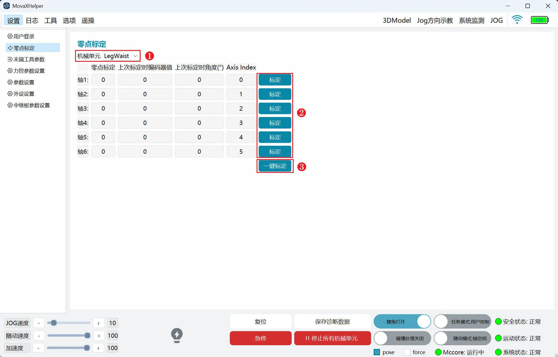
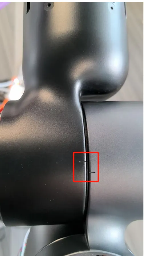
"Zero Point Calibration Function" refers to mechanical zero point calibration. The purpose is to make the robot's theoretical zero point coincide with the actual mechanical zero point. Zero point marking grooves are preset on the robot body. When each joint is aligned, that is, after returning to the mechanical zero point, calibration can be performed.
- ① Mechanical Unit: Select the mechanical unit for zero point calibration; generally, the mobile platform does not need zero point calibration;
- ② Calibration: Zero point calibration for a single joint;
- ③ One-click Calibration: Zero point calibration for all joints of the mechanical unit;
 |  |
|---|
Calibration steps are as follows. Hold the handheld emergency stop and maintain a certain distance from the robot:
- Power on a single mechanical unit through the "System Monitoring" page in the top status bar;
- Adjust "JOG Speed" to below 10 through the bottom status bar;
- Enter the "Jog" page on the right control panel to Jog until the joint zero position marking groove is aligned;
- Perform calibration through the "Zero Point Calibration" page. Note the distinction between "Calibration" (single joint calibration) and "One-click Calibration" (all joint calibration);
- Restart the controller to take effect.
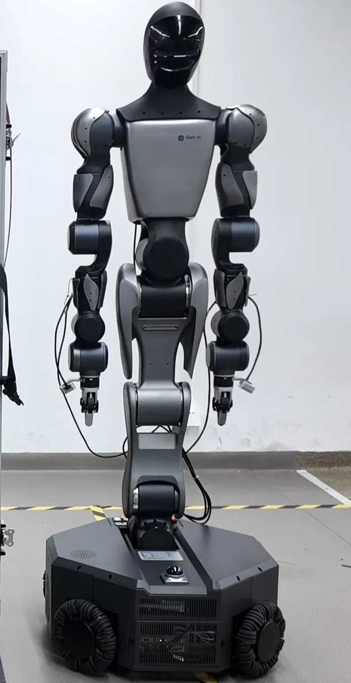
When all joints are at the zero point, the robot posture is as shown in the figure.
DANGER
Do not calibrate mechanical zero points at will. Before calibration, please use mechanical calibration blocks to confirm that all joints of the robot are at the zero point.
Peripheral Settings
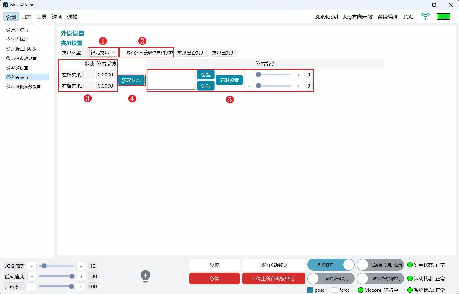
"Peripheral Settings" is used to adjust the opening and closing size of the two fingers at the end of the left and right arm grippers.
- ① Gripper Type: Select the end gripper type; the factory standard is Spirit gripper. If replacing with other gripper types, please contact technical support
- ② Real-time Get Position and Status: After checking, "Status" and "Position Feedback" in ③ update once per second; after checking, logs will be continuously refreshed, occupying backend resources. It is not recommended to check unless necessary
- ③ "Status" "Position Feedback": Gripper communication status and current position feedback; can be updated once per second by checking ② or obtained in real time through ④
- ④ Get Status: Get current gripper communication status and position feedback;
- ⑤ "Set" "Set Simultaneously": "Set" sets a single gripper, "Set Simultaneously" sets both grippers; effective range 0-12, unit: cm
- ⑥ Gripper Position Setting Control: Same function as ⑤, single gripper setting, maximum opening and closing distance 12cm
Teleoperation Settings
- Teleoperation system version display and teleoperation HMI version display
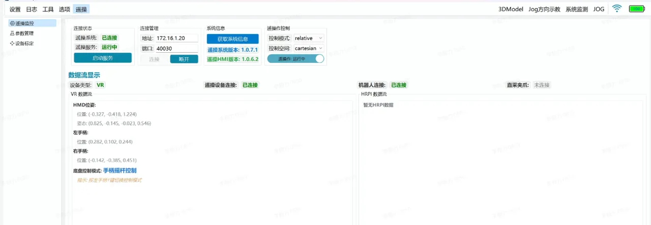
- Teleoperation system version display and teleoperation HMI version display
- The torso base coordinate system definition is moved up above the chassis;
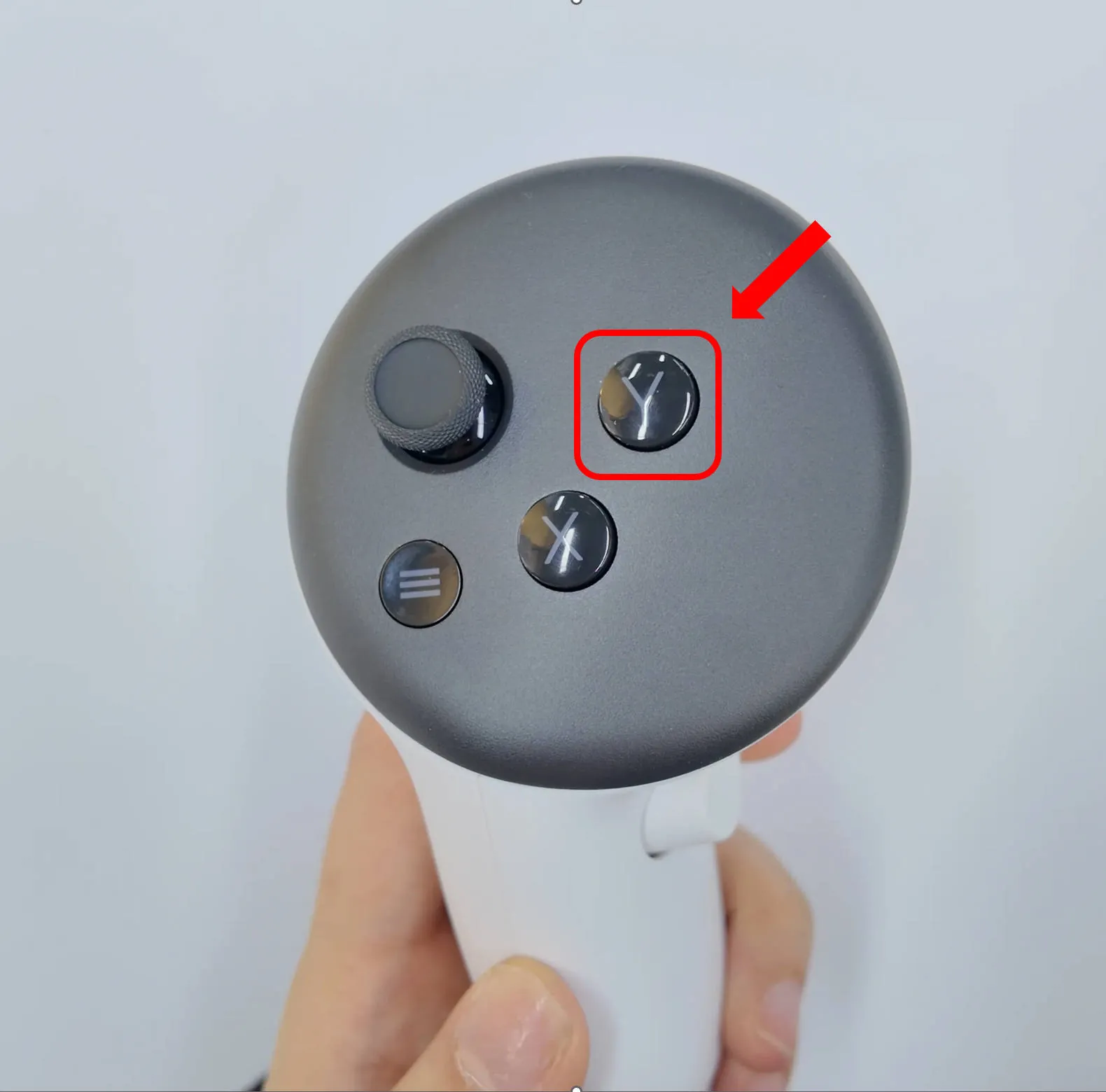
- Teleoperation adds head-mounted display control chassis mode, chassis control mode is switched through VR controller Y button: head-mounted display control or controller control; VR controller B button is the dual arm return button;
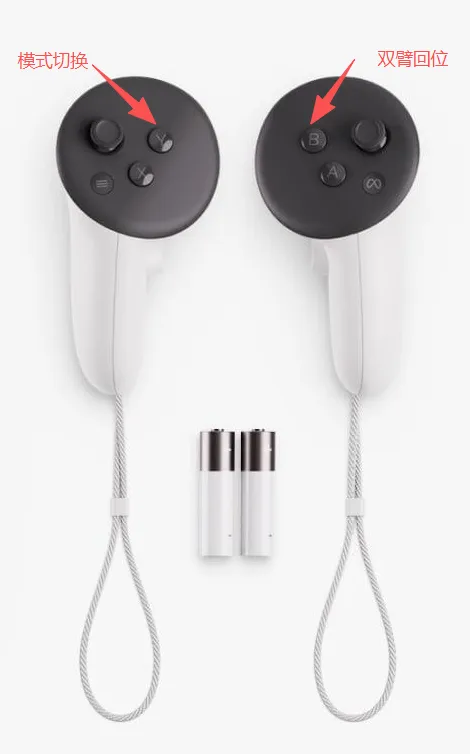
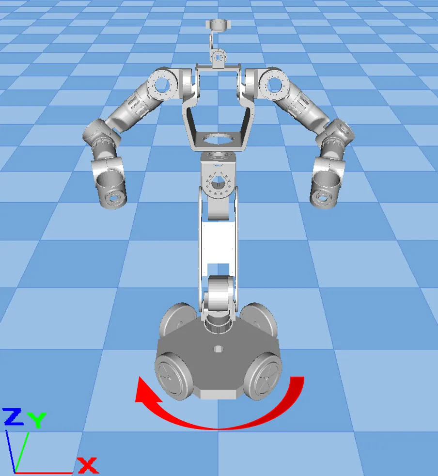
- When using VR for teleoperation, the joystick control chassis rotation direction changes from mirror rotation to same-direction rotation;
 |  |
|---|
- Teleoperation function improves connection stability and page usability: adds connection status information feedback on the page;
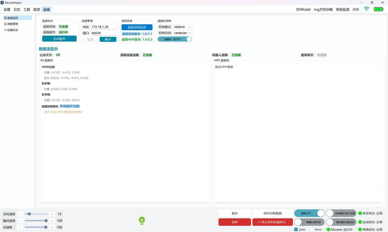
For detailed use of teleoperation, see the teleoperation section Get Started
Log
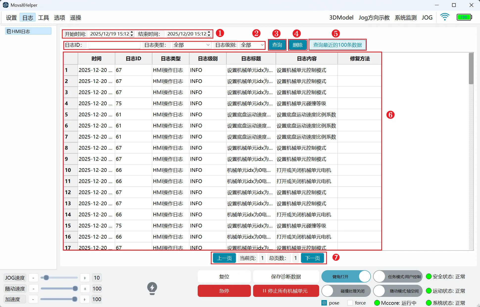
"HMI Log" is used to query past servo error information for corresponding handling.
- ① Log Time Control: Select log time interval;
- ② Log Filter Control: Log ID, Log Type, Log Level; currently only open to users for "Servo Error" type "ERROR" level log query function;
- ③ Query: Query logs according to the interval selected in ① and filter conditions in ②;
- ④ Delete: Delete logs from this query;
- ⑤ Query Latest 100 Records: Not restricted by ① and ②, query the latest 100 log information;
- ⑥ Log Information Display: Log information display, each page displays 100 items, browse by dragging the left slider;
- ⑦ Page Turn Control: Click to turn pages;
Version Upgrade
- Function Location: Options--Version Upgrade
movax Upgrade
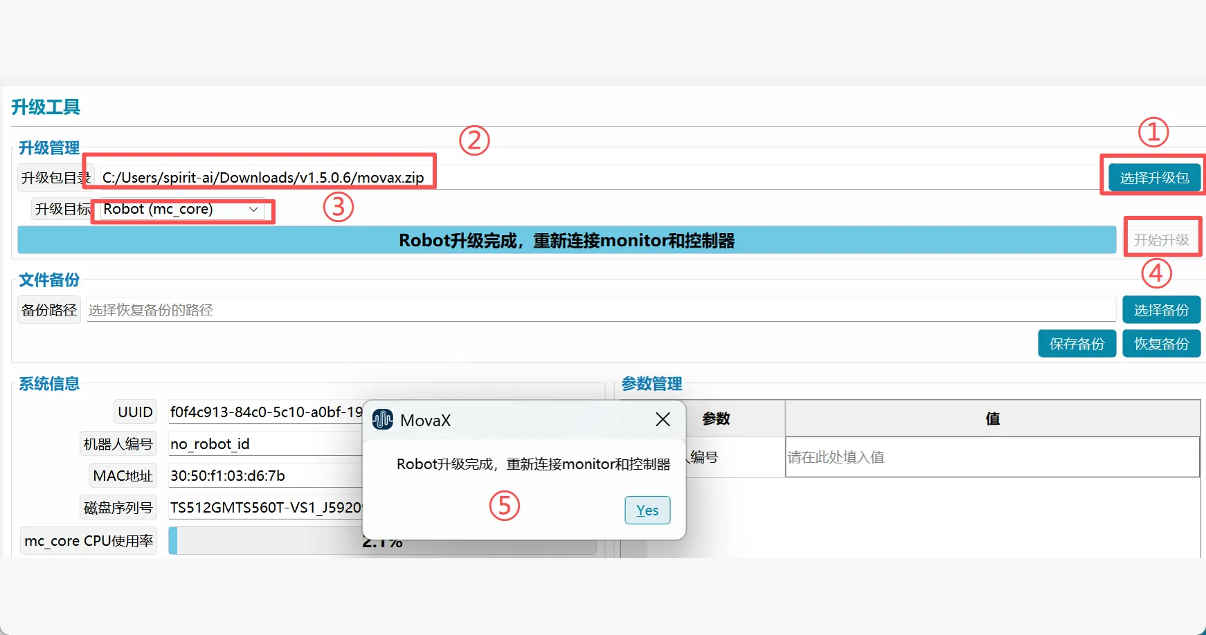
- Click "Select Upgrade Package";
- Select the movax.zip file stored in the local path. The upgrade package directory path display is based on the actual location;
- Select Robot(mc_core) as the upgrade target;
- Click Start Upgrade, wait for the upgrade to complete, click Connect Monitor and Start Controller according to the prompts;
moz_teleop Upgrade
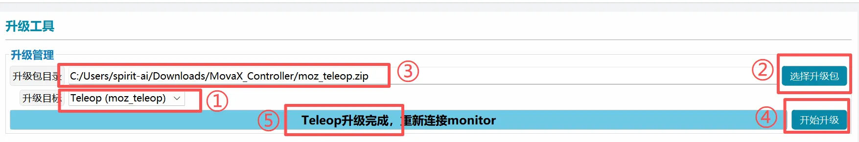
- Select Teleop(moz_teleop) as the upgrade target;
- Click Select Upgrade Package. The upgrade package directory path display is based on the actual location;
- Click Start Upgrade, wait for the upgrade to complete, restart the moz_teleop program
File Backup

- Select Backup: Select files or folders to back up;
- Save Backup: Back up the selected files or folders to prevent upgrade overwrites, parameter configuration loss, replacement, etc.;
- Restore Backup: Restore according to the backed up files or folders;
System Information
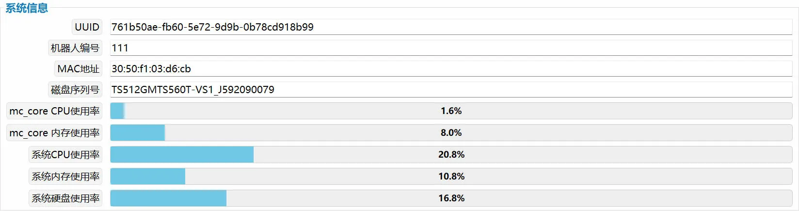
System information displays robot number, MAC address, mc_core_CPU usage, system CPU usage, system memory usage, and other information.