Teleoperation and Data Collection
INFO
Note: Teleoperation HMI version 1.0.3 update, please refer to the notes in each section.
Device Connection
Device List
External control mode devices (hereinafter referred to as "teleoperation") include Quest VR headset, VR controllers *2, and data cable connecting the computer to the robot controller.
Software includes MovaXHelper; note that Capture-X (data collection software) is not required for teleoperation only.
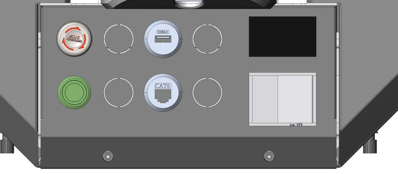
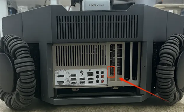
Connect the computer to the industrial PC (as shown in the figure below, CAT6 interface), connect the VR headset to the USB interface shown below, then turn on the VR device (VR power button is on the left side of the headset).
Device Startup and Connection
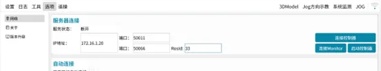
- Start MovaXHelper and enter the [Options] - [Network] interface. Default wired connection IP address: 172.16.1.20; wireless connects through the default assigned hotspot, hotspot name: Moz1-0900x (for example, device 1 is Moz-09001).
RosId is set to 33 by default and needs to match the teleoperation configuration in step two. After entering step two, click the WiFi button in the upper right corner to return to this interface.
 |
|---|
 |
|---|
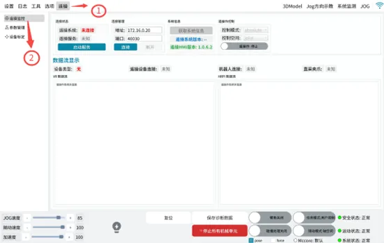
- Enter the teleoperation page for teleoperation configuration.
Check that the server IP and RosId settings are consistent with step one. Teleoperation port is set to 40030 by default.
 |
|---|
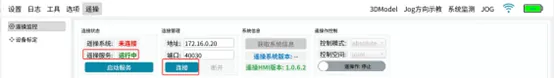
Make sure to click in order [Start Service (wait for teleoperation service to show running)] -> [If this is the first time starting teleoperation today, enter the VR headset and click to handle the popup] -> [Connect].
 |
|---|
After successful connection, the status shows "Connected":
 |
|---|
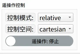
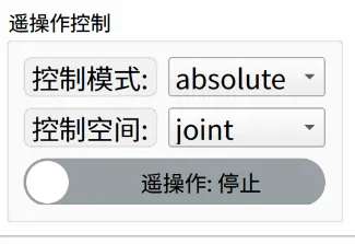
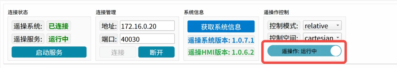
- (Default) In the [Teleoperation Settings] interface, select Relative and Cartesian in the teleoperation control section, and click [Start Teleoperation] below.
 |
|---|
 |
- Check VR device connection: After connecting to teleoperation, the VR headset displays a green screen by default indicating successful startup.
After successful startup, press the VR left controller menu button to start teleoperation (see controller function button layout below).
INFO
Controller Function Button Layout
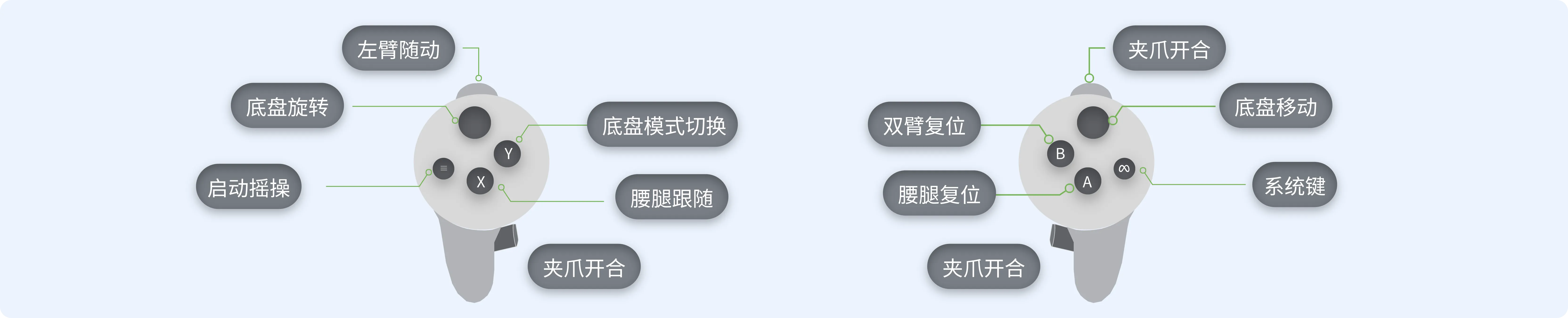
Left Controller:
- Menu Key: Start teleoperation
- X Key: Waist-leg following key; hold this key, robot waist-leg follows headset movement, stops when released
- Y Key: Switch base control mode through VR controller Y button
- Left Trigger: Left arm following key, hold this key, left arm follows movement
- Left Grip: Left gripper close key, grip to close, release to open
Right Controller:
- System Key: Quest system key in VR page; system takes over, can enter VR page for debugging
- A Key: Waist-leg reset key
- B Key: Dual arm reset key
- Right Trigger: Right arm following key, hold this key, right arm follows movement
- Right Grip: Right gripper close key, grip to close, release to open
- Thumbstick: Base forward/backward/left/right movement key
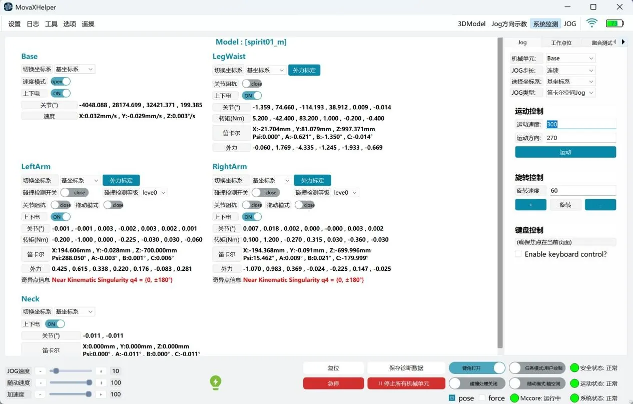
- Robot power on: Enter the [System Detection] interface, select the modules to power on, such as left arm, right arm, waist-leg.
DANGER
Note:
 |
|---|
The lightbulb lightning button below is for quick power on, not recommended for first-time operation.
It is recommended to power off when not in teleoperation mode to prevent accidental controller touches.
 |
|---|
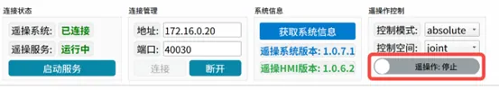
- After teleoperation ends, use the reset key on the controller, then click the teleoperation start button to turn off teleoperation control mode. The button turning gray indicates it is off.
 |
|---|
 |
VR Wearing Demonstration
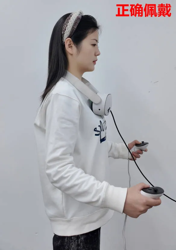
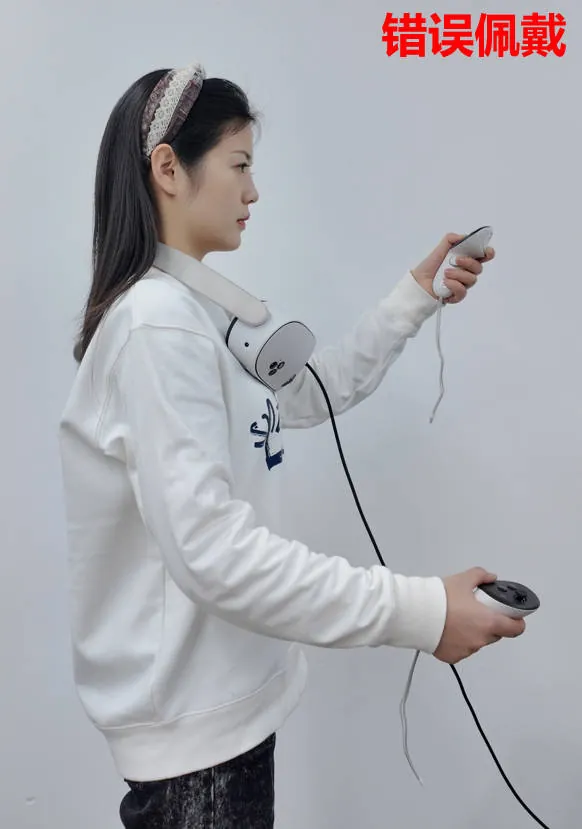
Correct wearing requires the VR device to be perpendicular to the head (Figure 1), incorrect wearing has the VR device not perpendicular to the head (Figure 2).
During teleoperation, the controller needs to be lower than the headset (Figure 1), teleoperation will fail if higher than the headset (Figure 2).
| Figure 1 | Figure 2 |
|---|---|
 |  |
Safety Precautions
It is recommended to reset after each teleoperation; please check if there are obstacles at the initial position before resetting.
Teleoperation Troubleshooting
Teleoperation service shows abnormal, not in running state:
(1) Check if mccore program is running normally;
(2) Whether connected to monitor;
(3) Check if VR is connected to the device;
(4) Check if VR is powered on;
(5) Check if VR has any popups;
(6) Check if ROS communication is normal, enter
ros2 topic listin terminal to check topic count;(7) Click start service again to check if service is normal;
Connection abnormal situations:
(1) Connection failed:
① Check if address is 172.16.0.20;
② Check if port number is 40030;
(2) Connection successful, teleoperation device connection abnormal:
① Check if VR and device connection cable is normal;
② Check VR device battery level;
③ Replace VR connection cable and reconnect;
④ Restart teleoperation service and reconnect to check if normal;
(3) Connection successful, robot connection abnormal:
① Check if ROS communication is normal;
② Check if mccore program is running normally;
③ Check if rosid is 33;
④ Check if 172.16.0.20 network can be pinged;
⑤ Check if network isolation is normal;
(4) Connection successful, gripper status abnormal:
① Check if the status light on the gripper is solid green;
② Check if the external communication cable of the gripper is normal, no obvious damage on the exterior;
③ Reconnect the gripper communication cable, restart teleoperation service and reconnect to check if gripper status is normal;
If none of the above can solve the problem encountered, please contact technical support for assistance.
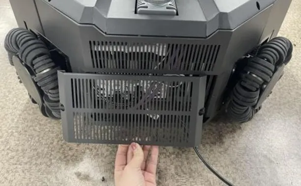
User Login
Open the external cover, connect the display (as shown below)
 |  |
|---|---|
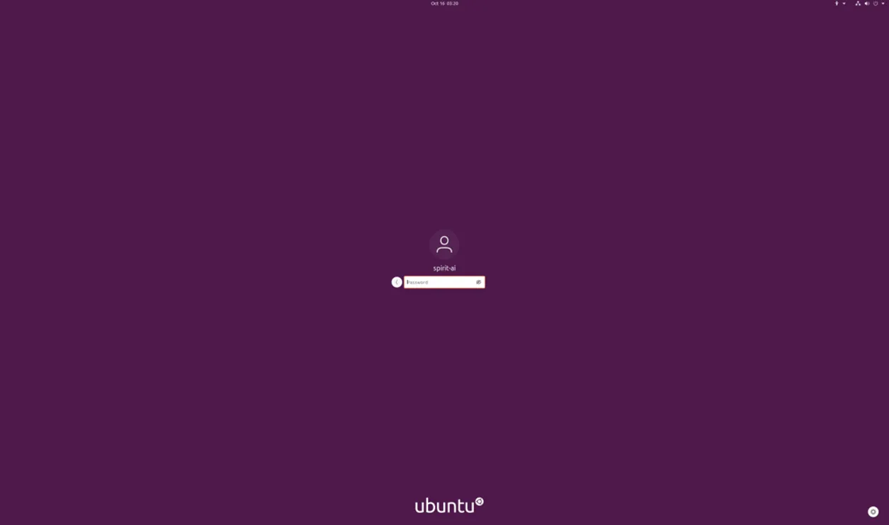
After connecting the display, Ubuntu login password is spirit-ai
 |
|---|
Login
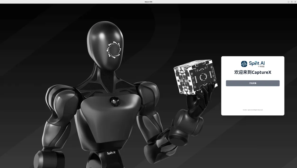
Enter HMI in command line to open data collection software
Login Interface
 |
|---|
Click start collection to enter the collection interface.
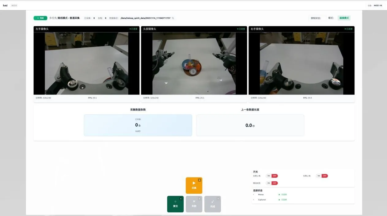
Login Data Collection System Functions
 |
|---|
Status and Information Display
Device Model Information
The upper right corner top displays device model information, such as MOZ1-xyz.
 |
|---|
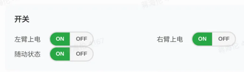
Switch Status Bar
The switch status bar section consists of three buttons, controlling left arm power on/off, right arm power on/off, and following status respectively. Following needs to be enabled for teleoperation; following is not recommended for inference (safety consideration); at other times it is recommended to turn off all three switches to prevent accidental teleoperation controller touches.
 |
|---|
Connection Status Bar
The connection status bar displays MovaX connection status.
 |
|---|
Data Collection Functions
Folder Path
The upper left corner of the interface shows the default generated data path, with copy function support. Current version does not support modification. The complete button returns to the login page.
Current version does not support automatic splitting of folders by failed and successful counts; please contact after-sales to obtain offline data splitting script.
 |
|---|
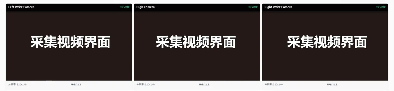
Camera Windows
Displays the top main camera and left/right hand secondary camera interfaces respectively.
 |
|---|
Data Information Bar and Operation Log
Displays collection count
 |
|---|
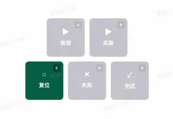
Keyboard Function Area Buttons
Function Pedal Indicators
- Inference (corresponds to keyboard A key) -- Enable inference mode for deployed model. Note that inference and collection modes are mutually exclusive.
- Collection (corresponds to keyboard B key) -- Start single data collection.
- Reset (corresponds to keyboard C key) -- Robot returns to initial pose. Click reset first, then click collect to ensure safety and data quality.
- Failed (corresponds to keyboard D key) -- Discard current data.
- Complete (corresponds to keyboard E key) -- Complete and record current data.
 |
|---|